
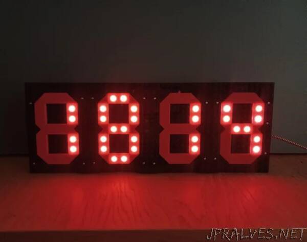
“This project makes use of a previous project Modular Display Element to make a digital clock, using four of the modules connected together and controlled by a Microbit and an RTC.
Supplies:
- Microbit V2 (preferred due to built in speaker, V1 will work but will require an external sounder.)
- DS3231 RTC
- Switch SPST
- Kitronik Edge Connector Breakout
- Jumper Jerky Junior F/M - Qty 20
- Jumper Jerky Junior F/F - Qty 4
- Jumper Jerky F/F - Qty 3
- Jumper Jerky F/M - Qty 3
- 470R resistor
- 1000uF capacitor
- Right Angle Header 2 x (3 ways x 1 row) required.
- WS2812Neopixel Button LED’s * 56 qty.
- Enamelled Copper Wire 21 AWG (0.75mm dia.), or other insulated wire.
- Stripboard
- Screws M2
- M2 screws 8mm - Qty 12
- M2 screws 6mm - Qty 16
- M2 Bolts 10mm - Qty 2
- M2 nuts - Qty 2
- M2 washers - Qty 2
- M2 Hex spaces 5mm - Qty 2
- Bolts M3
- M3 washers - Qty 14
- M3 bolts 10mm - Qty 2
- M3 bolts 25mm - Qty 4
- M3 nuts - Qty 12
- Hex standoffs M3
- M3 Hex spacers 5mm - Qty 2
- M3 Hex spacers 10mm - Qty 4
- Right angle Brackets (15(W) x 40(L) x 40(H) mm) - Qty 2”