
“Weather station with remote outdoor sense, FM radio, blinkey lights and secret hidden compartment.
Woodworker/ retired industrial automation engineer on steampunk kick. Have designed Rick & Morty gadgets and now want to take it to the next level.
Bought one of the full kits and wanted to see how far I could push it. Along the way I had to invent connector shrouds, cable holders, and lots of different 3D printed mounting hardware.
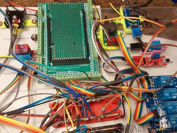
Once the wiring was decided and the mounts created the main components were mounted on a 112x1 piece of scrap lexan. I’ve got other lexan for the four LCD displays, optical pickups and indicators.
The unit is powered by a 12 volt DC car adapter connected to a TO-220 7805 three terminal +5 volt regulator. The +5, Gnd, SCL, and SDA lines are connected to buss bars for easy connection.
I tried a couple of different terminal shields. The ones with posts don’t keep a firm grip on the individual DuPont wires and the pin density makes adding new connections a fifty-fifty chance of knocking another pin loose.
Soldering to buss bars was chosen for simplicity and reliability. Mounts for 12 ga. buss bar wires were 3D printed and mounted. The mounts have the buss signal embossed for error free wiring.
Didn’t really consider the dissipation on that poor TO-220 package when dropping 12v to 5v at 2a. The drop is 7v @ 2a or 14W! After a while I noticed a curl of smoke from the mounting stand off. Oops! Need a Plan B.
One issue I have with running off the USB is that you have to unplug the project to turn it off. This will rapidly wear out the connectors. My solution was to splice in a switch on the USB power line so I can turn the project off and on without pulling the cables apart.
The DuPont cables have individual pins the need to be inserted. With most daughter cards having from two to eight pins, getting all to engage at once is a problem. Shrouds installed over the individual pins and glued in place allow the pins to be mated as a group as well as providing a labeling location.
Heat shrink tubing is used to prevent the ribbon wires from unzipping. Additionally it is used to separately group power leads and signal leads so wiring could be easily verified.
Each of the daughter cards supplied with the development kits have had cables and shrouds attached, as well as the mounting hardware loosely attached. This assembly was then bagged to keep all the necessary components in one place. This has greatly simplified installing as each assembly has been tested and is ready to go.
Most everything is working that’s been installed. The stepper motor is next to go in.
The dual 20x4 LCDs are handy as I’ve got diagnostic values being displayed from each sensor for easy debug in addition to the normal serial.print debugging messages.
One device I’m having issues with is the touch sensor. this should be a trivial item but seems to have a very noisy output. It looks like it’s chattering instead of giving a solid DO. The device also has an AO so maybe I can filter that.
The knock sensor is planned to be tied into the touch sensor so the user has to touch a certain screw of many on the panel and then trigger the knock. But that isn’t going to happen until I get the touch sensor working.
I’ve got the 5k pot, the internal +5 power and the external +12V supply all tied to AI’s so the system can monitor it’s internal voltages.
The 5k pot is looped into the servo and they track.
I want to wire up the DC motor but I also want to implement Motor direction/Enable logic so I need to add a 74LS00 quad NAND gate and an H-driver to reverse the motor. It’s not complex, but it’s gotta be built. Maybe give me something to solder into the breadboard area of the screw shield.
The RTC is sorta working, it’s stuck at the set time. I know I’m missing something simple but not highest on the priority list.
The sonar sounder was initially wired backward, reversing the bits in the code solved that without tinkering with the hardware.
The LDR for sundown sense is working. I’ve got it tied into the relay bank to turn on a load at dark. The relay can take 5A so I can control a significant load. Dunno WHAT yet, but I’m working on it.
Another thought. Could couple the laser with the LDR and make a pulsed beam system. This way the system can’t be dazzled by an outside source. We poll with the beam off and check to see that it’s dark. Then we turn the laser on and look again. If its now bright we’re ok and turn the laser back off. Since we’ve seen the beam in both states under our control we can be assured that the LDR is only seeing our beam and we can detect “dazzle”.
The remote EPS-01 is wired but is useless without someone else to comm with so that hasn’t been touched.
The DHT-11 is working fine. I have another one built into an EPS card that I need to figure out. Why doesn’t ANYTHING Arduino come with a pointer to the docs?
The four relays all work.
VU Meter Power
VU Source, NC - Radio, NO - AO
VU Mode - Pulse to change display mode
Darkness Relay, NC - Light, NO - Dark
Joystick is working, two analogs and a button. Mounting is still iffy. I can screw down the four corners but I have to buy a box of 100 6-32 x1” screws when I only NEED 4. (sigh)
IR remote was working on breadboard. Shouldn’t be hard to get running again. Have only decoded a few buttons. Need to get all 21 deciphered. This will allow remote control of the many functions of my Rick Box™.
Connections should be much more reliable since everything is mounted and not pulling on each other. I put some feet on the base. The entire rig can be lifted and moved without disturbing the wiring.”