
“What are we building?
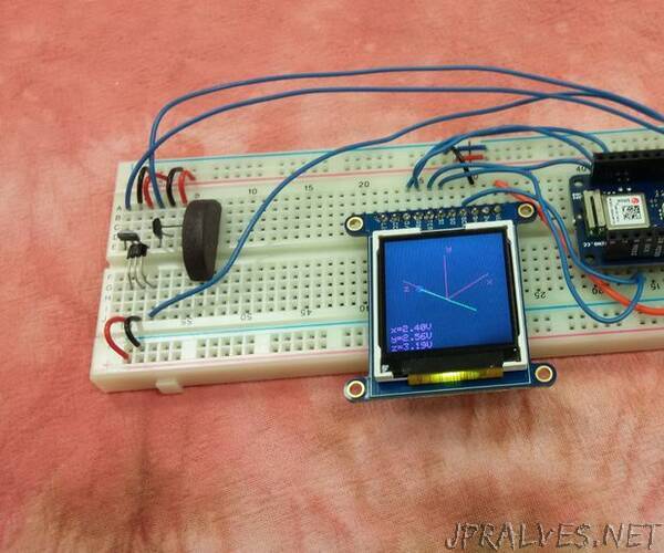
Humans can’t detect magnetic fields, but we use devices that rely on magnets all the time. Motors, compasses, rotation sensors, and wind turbines, for example, all require magnets for operation. This tutorial describes how to build an Arduino based magnetometer that senses magnetic field using three Hall effect sensors. The magnetic field vector at a location is displayed on a small screen using isometric projection.
What is an Arduino?
An Arduino is a small open-source user-friendly microcontroller. It has digital input and output pins. It also has analog input pins, which are useful for reading input from sensors. Different Arduino models are available. This tutorial describes how to use either the Arduino Uno or the Arduino MKR1010. However other models can be used too.
Before you begin this tutorial, download the Arduino development environment as well as any libraries needed for your particular model. The development environment is available at https://www.arduino.cc/en/main/software, and installation instructions are available at https://www.arduino.cc/en/main/software.
What is a magnetic field?
Permanent magnets exert forces on other permanent magnets. Current carrying wires exert forces on other current carrying wires. Permanent magnets and current carrying wires exert forces on each other too. This force per unit test current is a magnetic field.
If we measure the volume of an object, we get a single scalar number. However, magnetism is described by a vector field, a more complicated quantity. First, it varies with position throughout all space. For example, the magnetic field one centimeter from a permanent magnet is likely to be larger than the magnetic field ten centimeters away.
Next, the magnetic field at each point in space is represented by a vector. The magnitude of the vector represents the strength of the magnetic field. The direction is perpendicular to both the direction of the force and the direction of the test current.
We can picture the magnetic field at a single location as an arrow. We can picture the magnetic field throughout space by an array of arrow at different locations, possibly of different sizes and pointing in different directions. A nice visualization is available at https://www.falstad.com/vector3dm/. The magnetometer we are building displays the magnetic field at the location of the sensors as an arrow on the display.
What is a Hall effect sensor, and how does it work?
A Hall effect sensor is a small, inexpensive device that measures the strength of the magnetic field along a particular direction. It is made from a piece of semiconductor doped with excess charges. The output of some Hall effect sensors is an analog voltage. Other Hall effect sensors have an integrated comparator and produce a digital output. Other Hall effect sensors are integrated into larger instruments which measure flow rate, rotation speed, or other quantities.
The physics behind the Hall effect is summarized by the Lorentz force equation. This equation describes the force on a moving charge due to an external electric and magnetic field.
The figure below illustrates the Hall effect. Suppose we want to measure the strength of the magnetic field in the direction of the blue arrow. As shown in the left part of the figure, we apply a current through a piece of semiconductor perpendicular to the direction of the field to be measured. Current is flow of charges, so a charge in the semiconductor moves with some velocity. This charge will feel a force due to the external field, as shown in the middle part of the figure. Charges will move due to the force and accumulate on the edges of the semiconductor. Charges build up until the force due to the accumulated charges balances the force due to the external magnetic field. We can measure the voltage across the semiconductor, as shown in the right part of the figure. The voltage measured is proportional to the strength of the magnetic field, and it is in the direction perpendicular to the current and the direction of the magnetic field.
What is isometric projection?
At each point in space, the magnetic field is described by a three dimensional vector. However, our display screen is two dimensional. We can project the three dimensional vector into a two dimensional plane so that we can draw it on the screen. There are multiple ways to accomplish this such as isometric projection, orthographic projection, or oblique projection.
In isometric projection, the x, y, and z axes are 120 degrees apart, and they appear equally foreshortened. Additional information about isometric projection, as well as the formulas needed, can be found on Wikipedia’s page on the topic.”