
“One interesting aspect of a computer’s instruction set is its addressing modes, how the computer determines the address for a memory access. The Intel 8086 (1978) used the ModR/M byte, a special byte following the opcode, to select the addressing mode.1 The ModR/M byte has persisted into the modern x86 architecture, so it’s interesting to look at its roots and original implementation.
In this post, I look at the hardware and microcode in the 8086 that implements ModR/M2 and how the 8086 designers fit multiple addressing modes into the 8086’s limited microcode ROM. One technique was a hybrid approach that combined generic microcode with hardware logic that filled in the details for a particular instruction. A second technique was modular microcode, with subroutines for various parts of the task.
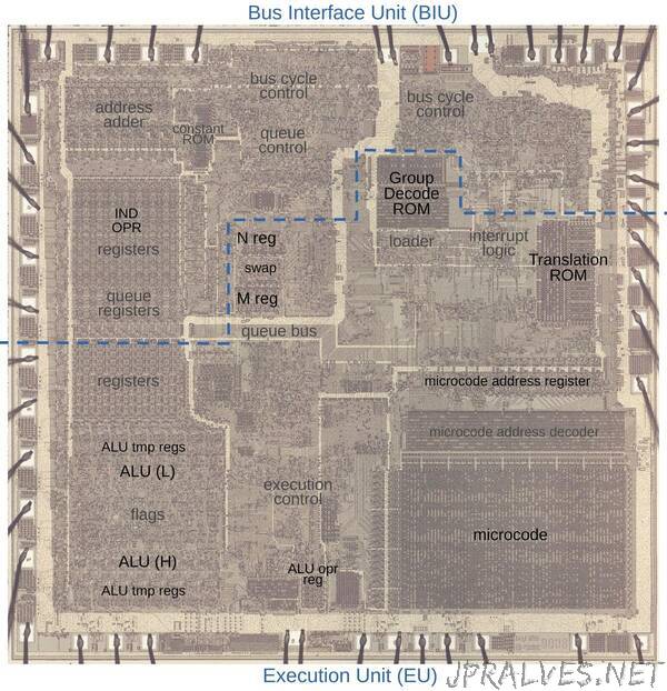
I’ve been reverse-engineering the 8086 starting with the silicon die. The die photo below shows the chip under a microscope. The metal layer on top of the chip is visible, with the silicon and polysilicon mostly hidden underneath. Around the edges of the die, bond wires connect pads to the chip’s 40 external pins. I’ve labeled the key functional blocks; the ones that are important to this discussion are darker and will be discussed in detail below. Architecturally, the chip is partitioned into a Bus Interface Unit (BIU) at the top and an Execution Unit (EU) below. The BIU handles bus and memory activity as well as instruction prefetching, while the Execution Unit (EU) executes instructions and microcode. Both units play important roles in memory addressing.
8086 addressing modes
Let’s start with an addition instruction, ADD dst,src, which adds a source value to a destination value and stores the result in the destination.3 What are the source and destination? Memory? Registers? The addressing mode answers this question.
You can use a register as the source and another register as the destination. The instruction below uses the AX register as the destination and the BX register as the source. Thus, it adds BX to AX and puts the result in AX.”