
“Intel introduced the 8086 microprocessor in 1978. This processor ended up being hugely influential, setting the path for the x86 architecture that is extensively used today. One interesting feature of the 8086 was instructions that can efficiently operate on blocks of memory up to 64K bytes long.1 These instructions rapidly copy, compare, or scan data and are known as “string” instructions.2
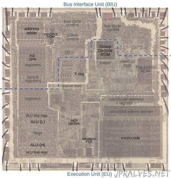
In this blog post, I explain string operations in the 8086, analyze the microcode that it used, and discuss the hardware circuitry that helped it out. My analysis is based on reverse-engineering the 8086 from die photos. The photo below shows the chip under a microscope. I’ve labeled the key functional blocks; the ones that are important to this post are darker. Architecturally, the chip is partitioned into a Bus Interface Unit (BIU) at the top and an Execution Unit (EU) below. The BIU handles memory accesses, while the Execution Unit (EU) executes instructions. The microcode ROM at the lower right controls the process.
Segments and addressing
Before I get into the details of the string instructions, I need to give a bit of background on how the 8086 accesses memory through segments. Earlier microprocessors such as the Intel 8080 (1974) used 16 bits to specify a memory address, allowing a maximum of 64K of memory. This memory capacity is absurdly small by modern standards, but at the time when a 4K memory board cost hundreds of dollars, this limit was not a problem. However, due to Moore’s Law and the exponential growth in memory capacity, the follow-on 8086 processor needed to support more memory. At the same time, the 8086 needed to use 16-bit registers for backward compatibility with the 8080.
The much-reviled solution was to create a 1-megabyte (20-bit) address space consisting of 64K segments, with a 16-bit address specifying a position within the segment. In more detail, the memory address was specified by a 16-bit offset address along with a particular 16-bit segment register selecting a segment. The segment register’s value was shifted by 4 bits to give the segment’s 20-bit base address. The 16-bit offset address was added, yielding a 20-bit memory address. This gave the processor a 1-megabyte address space, although only 64K could be accessed without changing a segment register. The 8086 had four segment registers so it could use multiple segments at the same time: the Code Segment, Data Segment, Stack Segment, and Extra Segment.
The 8086 chip is split into two processing units: the Bus Interface Unit (BIU) that handles segments and memory accesses, and the Execution Unit (EU) that executes instructions. The Execution Unit is what comes to mind when you think of a processor: it has most of the registers, the arithmetic/logic unit (ALU), and the microcode that implements instructions. The Bus Interface Unit interacts with memory and other external systems, performing the steps necessary to read and write memory.
Among other things, the Bus Interface Unit has a separate adder for address calculation; this adds the segment register to the base address to determine the final memory address. Every memory access uses the address adder at least once to add the segment base and offset. The address adder is also used to increment the program counter. Finally, the address adder increments and decrements the index registers used for block operations. This will be discussed in more detail below.
Microcode in the 8086
Most people think of machine instructions as the basic steps that a computer performs. However, many processors (including the 8086) have another layer of software underneath: microcode. With microcode, instead of building the control circuitry from complex logic gates, the control logic is largely replaced with code. To execute a machine instruction, the computer internally executes several simpler micro-instructions, specified by the microcode. This provides a considerable performance improvement for the block operations, which requires many steps in a loop. Performing this loop in microcode is considerably faster than writing the loop in assembly code.
A micro-instruction in the 8086 is encoded into 21 bits as shown below. Every micro-instruction specifies a move operation from a source register to a destination register, each specified with 5 bits. The meaning of the remaining bits depends on the type field and can be anything from an ALU operation to a memory read or write to a change of microcode control flow. Thus, an 8086 micro-instruction typically does two things in parallel: the move and the action. For more about 8086 microcode, see my microcode blog post.”