
“The Intel 8086 processor (1978) has a complicated instruction set with instructions ranging from one to six bytes long. This raises the question of how the processor knows the length of an instruction.1 The answer is that the 8086 uses an interesting combination of lookup ROMs and microcode to determine how many bytes to use for an instruction. In brief, the ROMs perform enough decoding to figure out if it needs one byte or two. After that, the microcode simply consumes instruction bytes as it needs them. Thus, nothing in the chip explicitly “knows” the length of an instruction. This blog post describes this process in more detail.
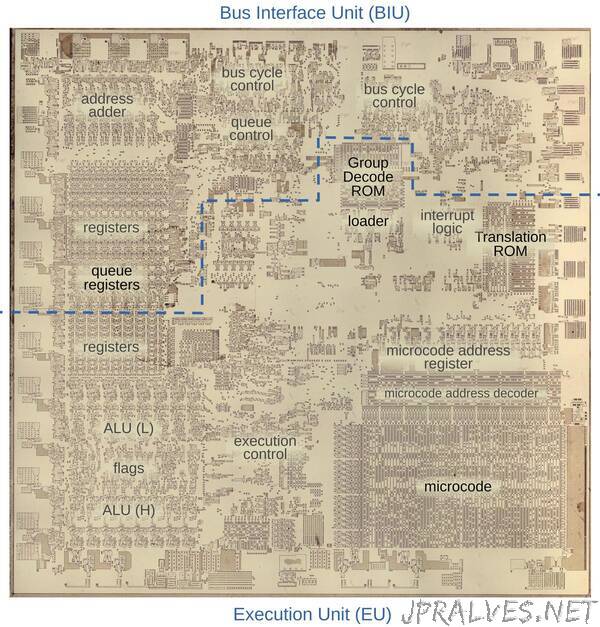
The die photo below shows the chip under a microscope. I’ve labeled the key functional blocks; the ones that are important to this post are darker. Architecturally, the chip is partitioned into a Bus Interface Unit (BIU) at the top and an Execution Unit (EU) below. The BIU handles bus and memory activity as well as instruction prefetching, while the Execution Unit (EU) executes the instructions.
The prefetch queue, the loader, and the microcode
The 8086 uses a 6-byte instruction prefetch queue to hold instructions, and this queue will play an important role in this discussion.3 Earlier microprocessors read instructions from memory as they were needed, which could cause the CPU to wait on memory. The 8086, instead, read instructions from memory before they were needed, storing them in the instruction prefetch queue. (You can think of this as a primitive instruction cache.) To execute an instruction, the 8086 took bytes out of the queue one at a time. If the queue ran empty, the processor waited until more instruction bytes were fetched from memory into the queue.
A circuit called the loader handles the interaction between the prefetch queue and instruction execution. The loader is a small state machine that provides control signals to the rest of the execution circuitry. The loader gets the first byte of an instruction from the prefetch queue and issues a signal FC (First Clock) that starts execution of the instruction.
At this point, the Group Decode ROM performs the first stage of instruction decoding, classifying the instruction into various categories based on the opcode byte. Most of the 8086’s instructions are implemented in microcode. However, a few instructions are so simple that they are implemented with logic circuits. For example, the CLC (Clear Carry) instruction clears the carry flag directly. The Group Decode ROM categorizes these instructions as 1BL (one-byte, implemented in logic). The loader responds by issuing an SC (Second Clock) signal to wrap up execution and start the next instruction. Thus, these simple instructions take two clock cycles.
The 8086 has various prefix bytes that can be put in front of an instruction to change its behavior. For instance, a segment prefix changes the memory segment that the instruction uses. A LOCK prefix locks the bus during the next instruction. The Group Decode ROM detects a prefix and outputs a prefix signal. This causes the prefix to be handled in logic, rather than microcode, similar to the 1BL instructions. Thus, a prefix also takes one byte and two clock cycles.
The remaining instructions are handled by microcode.2 Let’s start with a one-byte instruction such as INC AX, which increments the AX register. As before, the loader gets the instruction byte from the prefix queue. The Group Decode ROM determines that this instruction is implemented in microcode and can start after one byte, so the microcode engine starts running. The microcode below handles the increment and decrement instructions. It moves the appropriate register, indicated by M to the ALU’s temporary B register. It puts the incremented or decremented result (Σ) back into the register (M). RNI tells the loader to run the next instruction. With two micro-instruction, this instruction takes two clock cycles.”