
“Status flags are a key part of most processors, indicating if an arithmetic result is negative, zero, or has a carry, for instance. In this post, I take a close look at the flag circuitry in the Intel 8086 processor (1978), the chip that launched the PC revolution.1 Looking at the silicon die of the 8086 reveals how its flags are implemented. The 8086’s flag circuitry is surprisingly complicated, full of corner cases and special handling. Moreover, I found an undocumented zero register that is used by the microcode.
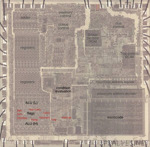
The die photo below shows the 8086 microprocessor under a microscope. The metal layer on top of the chip is visible, with the silicon and polysilicon mostly hidden underneath. Around the edges of the die, bond wires connect pads to the chip’s 40 external pins. I’ve labeled the key functional blocks; the ones that are important to this discussion are darker and will be discussed in detail below. The Arithmetic/Logic Unit (ALU, lower left) is split in two. The circuitry for the flags is in the middle, giving it access to the ALU’s results for the low byte and the high byte. I’ve marked each flag latch in red in the diagram below. They appear to be randomly scattered, but there are reasons for this layout.
Flags and arithmetic operations
The 8086 supports three types of arithmetic: unsigned arithmetic, signed arithmetic, and BCD (Binary-Coded Decimal) and this is a key to understanding the flags. Unsigned arithmetic uses standard binary values: a byte holds an integer value from 0 to 255, while a 16-bit word holds a value from 0 to 65535. When adding, a carry indicates that the result is too big to fit in a byte or word. (I’ll use byte operations to keep the examples small; operations on words are similar.) For instance, suppose you add hex 0x60 + 0x30. The result, 0x90, fits in a byte so there is no carry. But adding 0x90 + 0x90 yields 0x120. This result doesn’t fit in a byte, so the result is 0x20 with the carry flag set to 1. The carry allows additions to be chained together, like doing long decimal addition on paper. For subtraction, the carry bit indicates a borrow.
The second type of arithmetic is 2’s complement, which supports negative numbers. In a signed byte, 0x00 to 0x7f represent 0 to 127, while 0x80 to 0xff represent -128 to -1. If the top bit of a signed value is set, the value is negative; this is what the sign flag indicates. The clever thing about 2’s complement arithmetic is that the same instructions are used for unsigned arithmetic and 2’s complement arithmetic. The only thing that changes is the interpretation. As an example of signed arithmetic, 0xff + 0x05 = 0x04 corresponds to -1 + 5 = 4. Signed arithmetic can result in overflow, though. For example, suppose you add 112 + 112: 0x70 + 0x70 = 0xe0. Although that is fine in unsigned arithmetic, in signed arithmetic that result is unexpectedly -32. The problem is that the result doesn’t fit in a single signed byte. In this case, the overflow flag is set to indicate that the result overflowed. In other words, the carry flag indicates that an unsigned result doesn’t fit in a byte or word, while the overflow flag indicates that a signed result doesn’t fit.
The third type of arithmetic is BCD (Binary-Coded Decimal), which stores a decimal digit as a 4-bit binary value. Thus, two digits can be packed into a byte. For instance, adding 12 + 34 = 46 corresponds to 0x12 + 0x34 = 0x46 with BCD. After adding or subtracting BCD values, a special instruction is needed to perform any necessary adjustment.2 This instruction needs to know if there was a carry from the lower digit to the upper digit, i.e. a carry from bit 4 to bit 3. Many systems call this a half-carry, since it is the carry out of a half-byte, but Intel calls it the auxiliary carry flag.
The diagram below summarizes the 8086’s flags. The overflow, sign, auxiliary carry, and carry flags were discussed above. The zero flag simply indicates that the result of an operation was zero. The parity flag counts the number of 1 bits in a result byte and the flag is set if the number of 1 bits is even. At the left are the three control flags. The trap flag turns on single-stepping mode. The direction flag controls the direction of string operations. Finally, the interrupt flag enables interrupts.”