
“A key concept for a processor is the management of “state”, information that persists over time. Much of a computer is built from logic gates, such as NAND or NOR gates, but logic gates have no notion of time. Processors also need a way to hold values, along with a mechanism to move from step to step in a controlled fashion. This is the role of “sequential logic”, where the output depends on what happened before. Sequential logic usually operates off a clock signal,1 a sequence of regular pulses that controls the timing of the computer. (If you have a 3.2 GHz processor, for instance, that number is the clock frequency.)
A circuit called the flip-flop is a fundamental building block for sequential logic. A flip-flop can hold one bit of state, a “0” or a “1”, changing its value when the clock changes. Flip-flops are a key part of processors, with multiple roles. Several flip-flops can be combined to form a register, holding a value. Flip-flops are also used to build “state machines”, circuits that move from step to step in a controlled sequence. A flip-flops can also delay a signal, holding it from from one clock cycle to the next.
Intel introduced the groundbreaking 8086 microprocessor in 1978, starting the x86 architecture that is widely used today. In this blog post, I take a close look at the flip-flops in the 8086: what they do and how they are implemented. In particular, I will focus on the dynamic flip-flop, which holds its value using capacitance, much like DRAM.2 Many of these flip-flops use a somewhat unusual “enable” input, which allows the flip-flop to hold its value for multiple clock cycles.
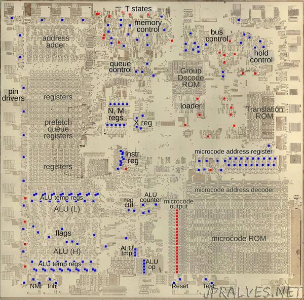
The die photo above shows the silicon die of the 8086. In this image, I have removed the metal and polysilicon layers to show the silicon transistors underneath. The colored squares indicate the flip-flops: blue flip-flops have an enable input, while red lack enable. Flip-flops are used throughout the processor for a variety of roles. Around the edges, they hold the state for output pins. The control circuitry makes heavy use of flip-flops for various state machines, such as moving through the “T states” that control the bus cycle. The “loader” uses a state machine to start each instruction. The instruction register, along with some special-purpose registers (N, M, and X) are built with flip-flops. Other flip-flops track the instructions in the prefetch queue. The microcode engine uses flip-flops to hold the current microcode address as well as to latch the 21-bit output from the microcode ROM. The ALU (Arithmetic/Logic Unit) uses flip-flops to hold the status flags, temporary input values, and information on the operation.”