
“What happens if you give the Intel 8086 processor an instruction that doesn’t exist? A modern microprocessor (80186 and later) will generate an exception, indicating that an illegal instruction was executed. However, early microprocessors didn’t include the circuitry to detect illegal instructions, since the chips didn’t have transistors to spare. Instead these processors would do something, but the results weren’t specified.1
The 8086 has a number of undocumented instructions. Most of them are simply duplicates of regular instructions, but a few have unexpected behavior, such as revealing the values of internal, hidden registers. In the 8086, most instructions are implemented in microcode, so examining the 8086’s microcode can explain why these instructions behave the way they do.
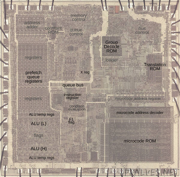
The photo below shows the 8086 die under a microscope, with the important functional blocks labeled. The metal layer is visible, while the underlying silicon and polysilicon wiring is mostly hidden. The microcode ROM and the microcode address decoder are in the lower right. The Group Decode ROM (upper center) is also important, as it performs the first step of instruction decoding.
Microcode and 8086 instruction decoding
You might think that machine instructions are the basic steps that a computer performs. However, instructions usually require multiple steps inside the processor. One way of expressing these multiple steps is through microcode, a technique dating back to 1951. To execute a machine instruction, the computer internally executes several simpler micro-instructions, specified by the microcode. In other words, microcode forms another layer between the machine instructions and the hardware. The main advantage of microcode is that it turns the processor’s control logic into a programming task instead of a difficult logic design task.
The 8086’s microcode ROM holds 512 micro-instructions, each 21 bits wide. Each micro-instruction performs two actions in parallel. First is a move between a source and a destination, typically registers. Second is an operation that can range from an arithmetic (ALU) operation to a memory access. The diagram below shows the structure of a 21-bit micro-instruction, divided into six types.
When executing a machine instruction, the 8086 performs a decoding step. Although the 8086 is a 16-bit processor, its instructions are based on bytes. In most cases, the first byte specifies the opcode, which may be followed by additional instruction bytes. In other cases, the byte is a “prefix” byte, which changes the behavior of the following instruction. The first byte is analyzed by something called the Group Decode ROM. This circuit categorizes the first byte of the instruction into about 35 categories that control how the instruction is decoded and executed. One category is “1-byte logic”; this indicates a one-byte instruction or prefix that is simple and implemented by logic circuitry in the 8086. For instructions in this category, microcode is not involved while the remaining instructions are implemented in microcode. Many of these instructions are in the “two-byte ROM” category indicating that the instruction has a second byte that also needs to be decoded by microcode. This second byte, called the ModR/M byte, specifies that memory addressing mode or registers that the instruction uses.
The next step is the microcode’s address decoder circuit, which determines where to start executing microcode based on the opcode. Conceptually, you can think of the microcode as stored in a ROM, indexed by the instruction opcode and a few sequence bits. However, since many instructions can use the same microcode, it would be inefficient to store duplicate copies of these routines. Instead, the microcode address decoder permits multiple instructions to reference the same entries in the ROM. This decoding circuitry is similar to a PLA (Programmable Logic Array) so it matches bit patterns to determine a particular starting point. This turns out to be important for undocumented instructions since undocumented instructions often match the pattern for a “real” instruction, making the undocumented instruction an alias.
The 8086 has several internal registers that are invisible to the programmer but are used by the microcode. Memory accesses use the Indirect (IND) and Operand (OPR) registers; the IND register holds the address in the segment, while the OPR register holds the data value that is read or written. Although these registers are normally not accessible by the programmer, some undocumented instructions provide access to these registers, as will be described later.
The Arithmetic/Logic Unit (ALU) performs arithmetic, logical, and shift operations in the 8086. The ALU uses three internal registers: tmpA, tmpB, and tmpC. An ALU operation requires two micro-instructions. The first micro-instruction specifies the operation (such as ADD) and the temporary register that holds one argument (e.g. tmpA); the second argument is always in tmpB. A following micro-instruction can access the ALU result through the pseudo-register Σ (sigma).”