
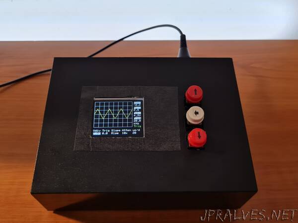
“Oscilloscope based around the STM32F401 Black Pill and a color LCD screen, meant to be used as an educational tool
Why does it exist?
The goal of this project was to create a simple and easy to build but still very usable oscillsocope. I wanted to learn the basics of how a digital storage oscilloscope functions, while also ending up with something which can be used as an educational tool in the lab. A short description of how oscillscopes (and this one in particular) work can be found here.
Features
- -3.3V to 3.3V input range (can be increased if using attenuator probes)
- 1MOhm input impedance
- 10uS/div minimum timebase
- 1.6 MSa/S sampling rate
- On screen measurements:
- min/max voltage
- peak-to-peak voltage
- frequency
- Captured waveforms can be sent to a computer over UART and analyzed in the Tektronix TekScope app
Required parts
Base parts:
- STM32F401CC Black Pill development board
- 128x160 ST7735-based TFT display
- 3 pushbuttons
- LM358 dual op-amp (rail-to-rail opamps should work better in this context, but this is what I had on hand)
- 2x 68kOhm resistors (to create a 1.65V offset voltage)
- 2x 500kOhm resistors (to create the input attenuator)
Useful, but not mandatory:
- a 5V power supply
- an opto-isolated USB UART adapter
- a BNC connector, for using proper oscilloscope probes”