
“Intel introduced the 8086 microprocessor in 1978, and its influence still remains through the popular x86 architecture. The 8086 was a fairly complex microprocessor for its time, implementing instructions in microcode with pipelining to improve performance. This blog post explains the microcode operations for a particular instruction, “ADD immediate”. As the 8086 documentation will tell you, this instruction takes four clock cycles to execute. But looking internally shows seven clock cycles of activity. How does the 8086 fit seven cycles of computation into four cycles? As I will show, the trick is pipelining.
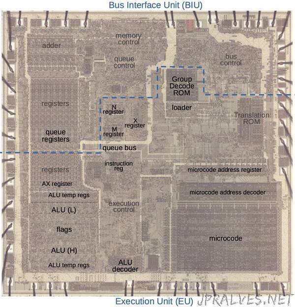
The die photo below shows the 8086 microprocessor under a microscope. The metal layer on top of the chip is visible, with the silicon and polysilicon mostly hidden underneath. Around the edges of the die, bond wires connect pads to the chip’s 40 external pins. Architecturally, the chip is partitioned into a Bus Interface Unit (BIU) at the top and an Execution Unit (EU) below, which will be important in the discussion. The Bus Interface Unit handles memory accesses (including instruction prefetching), while the Execution Unit executes instructions. The functional blocks labeled in black are the ones that are part of the discussion below. In particular, the registers and ALU (Arithmetic/Logic Unit) are at the left and the large microcode ROM is in the lower-right.
Microcode for “ADD”
Most people think of machine instructions as the basic steps that a computer performs. However, many processors (including the 8086) have another layer of software underneath: microcode. The motivation is that instructions usually require multiple steps inside the processor. One of the hardest parts of computer design is creating the control logic that directs the processor for each step of an instruction. The straightforward approach is to build a circuit from flip-flops and gates that moves through the various steps and generates the control signals. However, this circuitry is complicated, error-prone, and hard to design.
The alternative is microcode: instead of building the control circuitry from complex logic gates, the control logic is largely replaced with code. To execute a machine instruction, the computer internally executes several simpler micro-instructions, specified by the microcode. In other words, microcode forms another layer between the machine instructions and the hardware. The main advantage of microcode is that it turns the processor’s control logic into a programming task instead of a difficult logic design task.
The 8086 uses a hybrid approach: although the 8086 uses microcode, much of the instruction functionality is implemented with gate logic. This approach removed duplication from the microcode and kept the microcode small enough for 1978 technology. In a sense the microcode is parameterized. For instance, the microcode can specify a generic ALU operation, and the gate logic determines from the instruction which ALU operation to perform. Likewise, the microcode can specify a generic register and the gate logic determines which register to use. The simplest instructions (such as prefixes or condition-code operations) don’t use microcode at all. Although this made the 8086’s gate logic more complicated, the tradeoff was worthwhile.
The 8086’s microcode was disassembled by Andrew Jenner (link) from my die photos, so we can see exactly what micro-instructions the 8086 is running for each machine instruction. In this post, I will focus on the ADD instruction, since it is fairly straightforward. In particular, the “ADD AX, immediate” instruction contains a 16-bit value that is added to the value in the 16-bit AX register. This instruction consists of three bytes: the opcode 05, followed by the two-byte immediate value. (An “immediate” value is included in the instruction, rather than coming from a register or memory location.)
This ADD instruction is implemented in the 8086’s microcode as four micro-instructions, shown below. Each micro-instruction specifies a move operation across the internal ALU bus. It also specifies an action. In brief, the first two instructions get the immediate argument from the prefetch queue. The third instruction gets the argument from the AX register and starts the ALU (Arithmetic/Logic Unit) operation. The final instruction stores the result into the AX register and updates the condition flags.”