
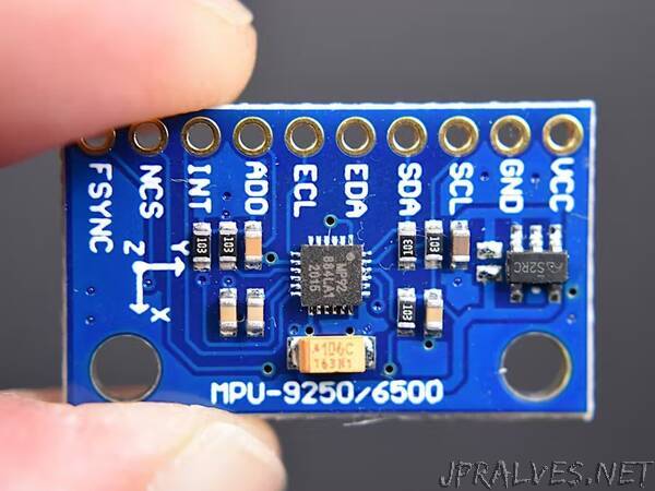
“MPU-9250 is one of the most advanced combined accelerometer, gyroscope and compass small size sensors currently available. It replaces the popular MPU-9150 lowering the power consumption, improving gyro noise and compass full scale range performance. It has many advanced features, including low pass filtering, motion detection and even a programmable specialized processor.
Internally it includes the MPU-6500, which contains a 3-axis gyroscope plus a 3-axis accelerometer, and the AK8963, the market leading 3-axis digital compass. The MPU-9250 uses 16-bit analog-to-digital converters (ADCs) for digitizing all 9 axes.
The MPU-9250 is a high performance accelerometer, gyroscope and magnetometer option for use in applications such as gesture recognition, self-balancing robots, cell phones, fitness monitoring and similar applications where detection of movement direction and magnitude along with rotation is desired. In reading MPU9250 sensors with Arduino article we’ve introduced the module and how to interact with it, now we will see how to use extracted data and get relative orientation.
Relative orientation
Relative orientation is the recovery of the position and orientation of one object relative to another. Depending on the direction there are three types of angular rate measurements:
- Yaw: the horizontal rotation on a flat surface when seen the object from above.
- Pitch: vertical rotation as seen the object from front.
- Roll: horizontal rotation when seen the object from front.
Accelerometer angles
Commonly, g is used as a unit for acceleration, relative to standard gravity (1g = 9.80665m/s2). Acceleration for perfectly aligned IMU will be 1g for Z axis. Terrestrial gravity and trigonometry allow to use the accelerometer readings and know the angle of inclination. The formulas to calculate the angles are:
pitch = atan2(accelerometer_x, sqrt(accelerometer_y^2 + accelerometer_z^2))
roll = atan2(accelerometer_y, sqrt(accelerometer_x^2 + accelerometer_z^2))
You can not obtain yaw angles from accelerometer because yaw motions occur in a plane and so no matter what X and Y readings you have.
Gyroscope angles
The gyroscope measures the angular velocity, i.e., the number of degrees rotated in a unit of time. Having initial angle of the IMU, angular velocity and the time passed between samples, we can know the angle change. It’s very similar to linear speed, that multiplied by time give us the total distance passed. The formulas to calculate the angles are:
pitch = pitch + gyroscope_x * elapsed_time
roll = roll + gyroscope_y * elapsed_time
yaw = yaw + gyroscope_z * elapsed_time
Where elapsed time is the time interval between samples. The Z axis is usually ignored, since we don’t have yaw angle from accelerometer and we can not rely only on gyroscope sensor.
Noise and errors
In the ideal word, sensors data with applied formulas would provide us precise and exact angles. The reality is different as some factors affect the sensors output.
Typically, when you move around with an accelerometer it experiences movement accelerations. Additional acceleration values may affect the orientation accuracy. Another accelerometer related problem is the noise: unwanted disturbance in an electrical signal. The accelerometer is able to measure any angle, however its readings are noisy and have a certain margin of error even with a low pass filter.
On the other hand, gyroscopes are subject to bias instabilities, in which the initial zero reading of the gyroscope will cause drift over time due to integration of inherent imperfections and noise within the device.
So, what can we do? There are different algorithms to solve this problems. The one we are going to use is known as complementary filter. Idea behind complementary filter is to take slow moving signals from accelerometer and fast moving signals from a gyroscope and combine them. It is ideal to implement with Arduino: easy to use, low cost of processing and good precision.
Complementary filters
The complementary filter can be thought of as a union of two different filters: a high-pass filter for the gyroscope and a low-pass filter for the accelerometer. The first lets only pass the values above a certain limit, unlike the low-pass filter, which only allows those below.
Accelerometer gives a good indicator of orientation in static conditions and gyroscope gives a good indicator of tilt in dynamic conditions. The formula resulting from combining the two filters is:
angle = (1 - α) * (angle + gyroscope * dt) + α * accelerometer
A common value for α is 0.98, which means that 98% of the weight lays on the gyroscope measurements.
pitch = 0.98 * (pitch + gyroscope_x * dt) + 0.02* accelerometer_x
roll = 0.98 * (roll + gyroscope_y * dt) + 0.02* accelerometer_y
As the data changes very rapidly we can sample for some amount of time and take the average for more precise results.”