
“Make your own logic level converter to convert 3V data to 5V and vice-versa
Did you ever tried connecting a 5V relay with Raspberry Pi or ESP8266 and faced issues switching it? This is basically because the relay works on 5V logic, and RPi and ESP8266 work on 3.3V. This leads to differences in the logic levels.
In recent times, with increasing demands for more power efficiency and high speeds of operation, a successive family of lower voltages came up in the market. Currently, the three most common logic levels are 1.8V, 3.3V, and 5V. Why these standards? The simple reason for this is these are the voltages required to activate the transistor logic of a board or IC.
Why 3.3V components don’t understand 5V logic?
Most of the electronic components you have worked with are the ones compatible with Arduino and similar microcontrollers. They use the 5V Transistor-Transistor Logic (TTL). Usually above 2V and pretty close to 5V is a logic 1 and below 0.8V is a logic 0.
When directly driving logic you’d normally use at 5V from a 3.3V output there is one cautionary tale of which to take heed, a personal confession of an electronic failure. CMOS logic defines its logic thresholds as a percentage of supply voltage, which with a 5V supply puts the logic 1 threshold of 70% well above the 3.3V logic 1. Some CMOS ICs such as the 74HC4053 analog switch I used in a Raspberry Pi project doesn’t quite follow this standard and will work from a 3.3V TTL output, so I was lulled into a false sense of security and reached for another 74HC part to connect to my Raspberry Pi with a new design. As you might expect it failed to work, and of course, I wasted time looking everywhere else but my defective choice of the part. If there is a moral to this story it is to always read the datasheet carefully, and use the TTL-compatible parts such as in this case 74HCT, when they are available.
If your 3.3V device inputs are not 5V tolerant and your 5V inputs lack 3.3V compatible thresholds then sadly you won’t be able to interface them across voltage levels without a shifter circuit. There are many choices available to you including a whole host of dedicated level shifter devices such as these ones from TI, but aside from personal preference some of them will be dictated by your application. Will it be step-up or a step-down, or do you need a bi-directional level shifter? If you decide not to use a dedicated part or a 5V tolerant gate in your design, here are a few of the many alternatives.
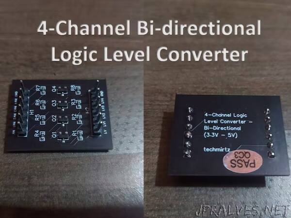
Bi-Directional Logic Shifter
A simple bidirectional logic level shifter is built around a single transistor and, as the switching speed is not an issue, is a very handy and convenient circuit.
When HIGH (pin) is logic1 (i.e., 5V at that pin), the drain and source of the MOSFET are pulled high. The gate voltage will be lower than the source voltage in this case and so MOSFET is in the cut-off region (i.e., inactive). Thus, the LOW pin is pulled at 3.3V as no current flows through the gate. When HIGH is logic0, the gate voltage is greater than the source voltage which will pull the LOW pin output down.
Similarly, when LOW is logic1, then Vgs (gate-source voltage) will be 0 and so the transistor will be inactive pulling the HIGH pin to +5V. When LOW is logic0, the gate voltage is again higher than the source voltage, and the HIGH pin is pulled down.”