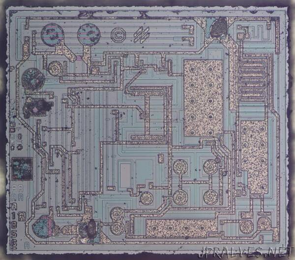
“Many circuits, such as a computer power supply or a phone charger, require a stable voltage reference, but it’s harder than you might expect to keep a voltage stable when the temperature changes. One integrated circuit that does this is the LM185.1 I looked at the die of this chip and found some interesting features. The same silicon die is used for three different integrated circuits, using tiny internal fuses to change its functionality. The chip uses a special circuit called the bandgap reference to keep the voltage stable even if the temperature changes. In this blog post, I’ll discuss the circuitry of the LM185 and its implementation in silicon.
The photo above shows the LM185 die under the microscope, a tiny square of silicon. The underlying silicon is blue-gray, while the metal wiring on top is orangish. Regions of the silicon are doped with various impurities to form the transistors, resistors, and other devices on the chip. The variations in doping are visible as slight color changes in the silicon. At the top is the National Semiconductor logo.
The LM185 is available in three variants. The LM185-ADJ is the adjustable voltage reference. It has three pins: one is a feedback pin that controls the voltage. The LM185-1.2-N is a two-pin device, called a “micropower voltage reference diode”. It is similar to a Zener diode providing 1.235V, but with better performance. (Lower power consumption, less noise, and better stability.) Finally, the LM185-2.5-N provides a 2.5V reference. The three variants are based on the same silicon die. The latter two have the feedback wired internally to provide a fixed voltage rather than an adjustable voltage.
The next sections describe how the various components of the chip are fabricated from silicon, and how they appear on the die.”
