
“The groundbreaking Intel 386 processor (1985) was the first 32-bit processor in the x86 line. It has numerous internal registers: general-purpose registers, index registers, segment selectors, and more specialized registers. In this blog post, I look at the silicon die of the 386 and explain how some of these registers are implemented at the transistor level. The registers that I examined are implemented as static RAM, with each bit stored in a common 8-transistor circuit, known as “8T”. Studying this circuit shows the interesting layout techniques that Intel used to squeeze two storage cells together to minimize the space they require.
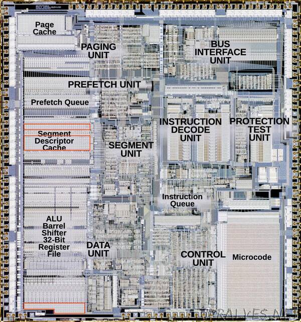
The diagram below shows the internal structure of the 386. I have marked the relevant registers with three red boxes. Two sets of registers are in the segment descriptor cache, presumably holding cache entries, and one set is at the bottom of the data path. Some of the registers at the bottom are 32 bits wide, while others are half as wide and hold 16 bits. (More registers with different circuits, but I won’t discuss them in this post.)
The 6T and 8T static RAM cells
First, I’ll explain how a 6T or 8T static cell holds a bit. The basic idea behind a static RAM cell is to connect two inverters into a loop. This circuit will be stable, with one inverter on and one inverter off, and each inverter supporting the other. Depending on which inverter is on, the circuit stores a 0 or a 1.
To write a new value into the circuit, two signals are fed in, forcing the inverters to the desired new values. One inverter receives the new bit value, while the other inverter receives the complemented bit value. This may seem like a brute-force way to update the bit, but it works. The trick is that the inverters in the cell are small and weak, while the input signals are higher current, able to overpower the inverters.1 The write data lines (called bitlines) are connected to the inverters by pass transistors.2 When the pass transistors are on, the signals on the write lines can pass through to the inverters. But when the pass transistors are off, the inverters are isolated from the write lines. Thus, the write control signal enables writing a new value to the inverters. (This signal is called a wordline since it controls access to a word of storage.) Since each inverter consists of two transistors7, the circuit below consists of six transistors, forming the 6T storage cell.”