
“The Intel 8086 microprocessor (1978) revolutionized computing by founding the x86 architecture that continues to this day. One of the lesser-known features of the 8086 is the “hold” functionality, which allows an external device to temporarily take control of the system’s bus. This feature was most important for supporting the 8087 math coprocessor chip, which was an option on the IBM PC; the 8087 used the bus hold so it could interact with the system without conflicting with the 8086 processor.
This blog post explains in detail how the bus hold feature is implemented in the processor’s logic. (Be warned that this post is a detailed look at a somewhat obscure feature.) I’ve also found some apparently undocumented characteristics of the 8086’s hold acknowledge circuitry, designed to make signal transition faster on the shared control lines.
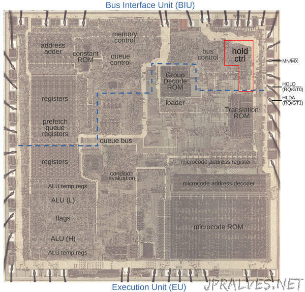
The die photo below shows the main functional blocks of the 8086 processor. In this image, the metal layer on top of the chip is visible, while the silicon and polysilicon underneath are obscured. The 8086 is partitioned into a Bus Interface Unit (upper) that handles bus traffic, and an Execution Unit (lower) that executes instructions. The two units operate mostly independently, which will turn out to be important. The Bus Interface Unit handles read and write operations as requested by the Execution Unit. The Bus Interface Unit also prefetches instructions that the Execution Unit uses when it needs them. The hold control circuitry is highlighted in the upper right; it takes a nontrivial amount of space on the chip. The square pads around the edge of the die are connected by tiny bond wires to the chip’s 40 external pins. I’ve labeled the MN/MX, HOLD, and HLDA pads; these are the relevant signals for this post.
How bus hold works
In an 8086 system, the processor communicates with memory and I/O devices over a bus consisting of address and data lines along with various control signals. For high-speed data transfer, it is useful for an I/O device to send data directly to memory, bypassing the processor; this is called DMA (Direct Memory Access). Moreover, a co-processor such as the 8087 floating point unit may need to read data from memory. The bus hold feature supports these operations: it is a mechanism for the 8086 to give up control of the bus, letting another device use the bus to communicate with memory. Specifically, an external device requests a bus hold and the 8086 stops putting electrical signals on the bus and acknowledges the bus hold. The other device can now use the bus. When the other device is done, it signals the 8086, which then resumes its regular bus activity.
Most things in the 8086 are more complicated than you might expect, and the bus hold feature is no exception, largely due to the 8086’s minimum and maximum modes. The 8086 can be designed into a system in one of two ways—minimum mode and maximum mode—that redefine the meanings of the 8086’s external pins. Minimum mode is designed for simple systems and gives the control pins straightforward meanings such as indicating a read versus a write. Minimum mode provides bus signals that were similar to the earlier 8080 microprocessor, making migration to the 8086 easier. On the other hand, maximum mode is designed for sophisticated, multiprocessor systems and encodes the control signals to provide richer system information.
In more detail, minimum mode is selected if the MN/MX pin is wired high, while maximum mode is selected if the MN/MX pin is wired low. Nine of the chip’s pins have different meanings depending on the mode, but only two pins are relevant to this discussion. In minimum mode, pin 31 has the function HOLD, while pin 30 has the function HLDA (Hold Acknowlege). In maximum mode, pin 31 has the function RQ/GT0’, while pin 30 has the function RQ/GT1’.
I’ll start by explaining how a hold operation works in minimum mode. When an external device wants to use the bus, it pulls the HOLD pin high. At the end of the current bus cycle, the 8086 acknowledges the hold request by pulling HLDA high. The 8086 also puts its bus output pins into “tri-state” mode, in effect disconnecting them electrically from the bus. When the external device is done, it pulls HOLD low and the 8086 regains control of the bus. Don’t worry about the details of the timing below; the key point is that a device pulls HOLD high and the 8086 responds by pulling HLDA high.”