
“If you’ve played around with electronic circuits, you probably know the 555 timer integrated circuit,1 said to be the world’s best-selling integrated circuit with billions sold. Designed by analog IC wizard Hans Camenzind2, the 555 has been called one of the greatest chips of all time.
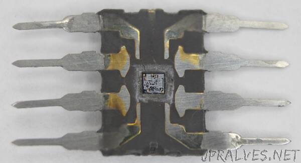
Eric Schlaepfer (@TubeTimeUS) recently came across the chip above, with a mysterious part number. He tediously sanded through the epoxy package to reveal the die (below) and determined that the chip is a 555 timer. Signetics released the 555 timer in mid-1972 4 and the chip below has a January 1973 date code (7304), so it must be one of the first 555 timers. Curiously, it is not labeled 555, so perhaps it is a prototype or internal version.3 I took detailed die photos, which I discuss in this blog post.
A brief explanation of the 555 timer
The 555 timer has hundreds of applications, operating as anything from a timer or latch to a voltage-controlled oscillator or modulator. The diagram below illustrates how the 555 timer operates as a simple oscillator. Inside the 555 chip, three resistors form a divider generating references voltages of 1/3 and 2/3 of the supply voltage. The external capacitor will charge and discharge between these limits, producing an oscillation. In more detail, the capacitor will slowly charge (A) through the external resistors until its voltage hits the 2/3 reference. At that point (B), the upper (threshold) comparator switches the flip flop off and the output off. This turns on the discharge transistor, slowly discharging the capacitor (C). When the voltage on the capacitor hits the 1/3 reference (D), the lower (trigger) comparator turns on, setting the flip flop and the output, and the cycle repeats. The values of the resistors and capacitor control the timing, from microseconds to hours.
To summarize, the key components of the 555 timer are the comparators to detect the upper and lower voltage limits, the three-resistor divider to set these limits, and the flip flop to keep track of whether the circuit is charging or discharging. The 555 timer has two other pins (reset and control voltage) that I haven’t covered above; they can be used for more complex circuits.”