
“The Yamaha DX7 digital synthesizer (1983) was the classic synthesizer for 1980s pop music. It used two custom digital chips to generate sounds with FM synthesis. In this blog post, I examine the log-sine ROM that digitally produces sine waves inside one of these chips. (This blog post jumps into the details; unless you care about the sine values specifically, my previous DX7 reverse-engineering article is probably more interesting.)
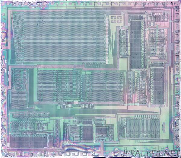
I created the high-resolution die photo below by compositing over a hundred microscope photos. I removed the metal layer from the chip with acid to reveal the silicon and polysilicon wiring underneath. You can see the structure of the functional blocks and the connections between them. The colors are due to variations in thickness of the oxide layer, causing thin-film interference. With the metal layer removed, I could read out the bits from the ROM, reverse-engineer the circuitry, and determine the exact values used for sine-wave generation.
Instead of the analog oscillators and filters of an analog synthesizer, the DX7 generates sounds digitally, using a technique called FM synthesis. The idea is that you start with a sine wave (the carrier signal) and perturb it with another signal (the modulating signal). The modulating signal changes the phase (and thus the frequency) of the carrier, creating complex harmonic structures like the waveform below. These signals are represented as digital values throughout the system; a digital-to-analog converter (DAC) turns the digital representation into an analog voltage for the synthesizer’s output.”