
“Make your own TV remote!
My girlfriend’s TV remote control stopped working. She could have bought a cheap replacement at a store nearby, but then she thought: we are both engineers, let’s make our own one together!
As we are quite complementary in our skills, this was a different, but fun way to spend some time during lockdown and it gave us the opportunity to learn a bit about how this everyday technology works.
Oh, and having a small 3D-printer at home also played a role.
How it works
First of all, as we wanted to make a simple design reliying on the Arduino UNO, we evaluated the minimum number of commands that we needed to operate our TV. We considered that 6 commands were enough: ON/OFF toggle, Source selection, Ch+, Ch-, Vol+, Vol-.
Button reading
To avoid the use of additional resistors, the design relies on the internal pull-up resistors of the Arduino. If the remote control is not in sleep mode (see below), each button state is polled in each loop cycle. To avoid counting multiple hits, a simple debouncing routine is implememnted exploiting the millis() function.
Sending infrared signals
Infrared communication is dealt by the IRremote.h library (kudos to the coders!). All we had to do was to setup the protocol for our tv (different manufacturers have developed their own protocols) and search on Google for the codes in HEX of the different commands we wanted to use and associate them to the buttons. As it concerns the circuit design, to have the commands from the library effectively piloting the IR LED, this must be connected to pin3 of the Arduino UNO.
Currently, the code is written for three different types of tv, selectable by commenting/uncommenting a #define directive in the first part of code.
Batterysaving
To reduce power consumption, a few strategies are implemented, exploiting the commands from the avr/sleep.h and avr/power.h libraries.
All the unused peripherals and interfaces (ADC, SPI, TWI, timer1, usart) are turned off in the setup routine. The built-in LED on PWM pin13 is also turned off. We also decided to desolder the power LED of the Arduino UNO, which otherwise is always on, although it’s not a recommended operation.
Also, exploiting the millis(), if none of the button is pressed for 5 seconds the remote control enters a sleep mode, from which is woken up when the On/Off button is pressed again.
How it’s built
Electronicsassembly
The whole circuitry is embedded on a prototyping board, designed to fit on the Arduino UNO headers. By using a soldering iron, the buttons were soldered considering the final position on the remote. On the bottom part, the two 47ohm resistors were soldered in parallel, in order to achieve the desired current through the IR LED.
Using the solder wire, traces were made on the prototyping board to connect the button pins and the IR LED to male pin headers.
In this way, the board resembles a shield which is fitted on the Arduino UNO using the pin headers, ensuring all the correct connections.
EnclosureCADandCAM
The enclosure was designed to contain the battery, the Arduino UNO + prototyping board assembly, exposing only the buttons on the top and the IR LED on the front side.
The enclosure consists of two parts, designed using SolidWorks CAD software, pre-processed with Ultimaker Cura slicing software and finally 3D printed in PLA using an Anycubic Mega Zero 3D-printer.
The Arduino UNO is secured to the base by using 3 M2.5 screws, which fit in alignment holes extruded from the inside of the base. Once the Arduino is secured, the IR LED will protrude outside the prototyping board, in order to align it with the purpose built-hole and to keep it in position while assembling the two parts of the enclosure, three mini-posts are added to avoid lateral movements of the LED leads. The battery is press-fitted into a dedicated space.
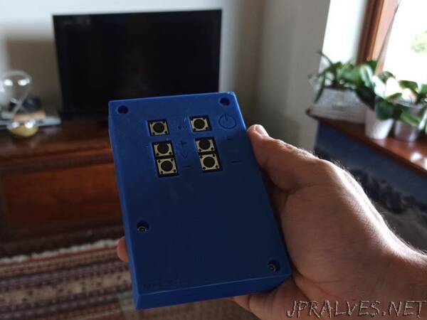
The cover is designed in order to expose only the buttons and besides each of them, a symbol is engraved in the cover to show the function of each button.
Base and cover of the enclosure are assembled using 4 M3 screws.”