
“Introduction
I’ve recently become interested in clock projects, and it seemed appropriate to start by building the essential digital clock assembled from logic chips. Although clock projects exactly like this have been around for the best part of 50 years at this point, I wanted to work it all out for myself, so I had a good read through Don Lancaster’s CMOS Cookbook for inspiration.
Hardware
The timebase is a typical 32.768kHz watch crystal, divided down to 1Hz using a 4060 counter into a 4013 flip-flop. It’s not the most accurate timebase, but it’s good enough. I thought about going the other route and deriving the timebase from the mains line frequency, but decided against it as I would like to be able to run the clock from a DC power source should I ever want to, rather than being tied to using an AC transformer (on a 50Hz supply as well).
This 1Hz clock signal goes into a chain of 4029 counters, to count the seconds, minutes and hours; each counting the 1s and 10s separately. An AND gate detects when the seconds count reaches 60, resetting it back to 0 and incrementing the minutes counter; which in turn does the same for the hours counter. Each 4029 outputs a 4-bit BCD value which goes to a 4511 BCD to 7-segment decoder to drive the LED displays. There’s also a circuit to reset the system to 00:00:00 at power-on, as well as a switch to set the time by sending the 1Hz clock into the minutes and hours counters.
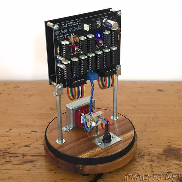
The functions are split across two PCBs, linked by a pair of ribbon cables. Power supply, 1Hz timebase, counters and reset circuitry are all on the first board (Counter Board); while the BCD decoders and LED displays are found on the second board (Display Board). Although I do feel that they can come off as tacky, I used blue LEDs for this as they’re a bit more eye-catching. It took a lot of experimentation to get the brightness to a tasteful level though, using 4K7 DIP series resistors for the 7-segment displays and 10K resistors for the individual LEDs.
Construction
I wanted something a bit more interesting looking than a rather utilitarian project box, so I opted to house it all in a glass dome with a nice wooden base. The boards are sandwiched together using M3 hex spacers, with the whole assembly supported from the base using some 75mm M3 spacers and angle brackets. This leaves room underneath for the mains transformer, fuse and cable (which leaves through a grommet on a small metal plate).
Conclusion
Apart from being a complete fingerprint magnet, I’m really pleased with how this one turned out. I really enjoyed the challenge of doing the whole thing with CMOS logic chips – not a line of code in sight! I’m already thinking about doing another with an alternative binary display board (which would be really easy as the counter board already outputs 4-bit BCD for each of the six digits). Beyond that, who knows – maybe a CMOS Calendar?”