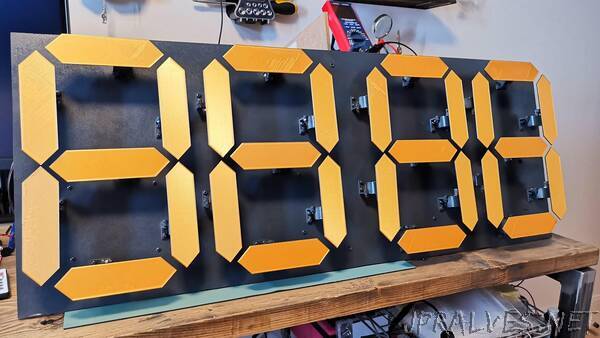
“The goal here was two-fold; create something stylish that would look good when hung up on a wall, and ensure that all movements were as quiet as possible! I was inspired by some great existing projects that I have bookmarked below, but most had used noisy servos. Using my idea to retrofit silent stepper drivers from 3D printers, I built, tested and coded my clock completely from scratch over 2-3 months of my spare time.
Motor choice.
For the purpose of making all movements as quiet as possible, I wanted to completely avoid using servo motors (which ruled out 5 of my 6 inspirations…). Servos are not designed for silent operation. Even some of the high-end servos I have from Robotis are pretty loud.
So I grabbed some of the most popular stepper motors out there; the 28BYJ-48 (12V versions). With internal gears, I still had my doubts in terms of the noise output.
Initial stepper driver test.
As a first basic test I connected a 28BYJ-48 motor to an Adafruit TB6612 pre-driver board which I had available (12V supply not shown connected here).
This initial test just used a basic SW example: https://www.arduino.cc/en/Reference/StepperSetSpeed
Compared to any servo the noise levels were much better here. However the conclusion from this test was that a “normal” stepper driver like the TB6612 wasn’t doing enough to reduce noise from the motor and gears.
Using silent stepper drivers.
TMC2208-V3.0 from BIGTREETECH. These modules are used primarily in 3D printers to ensure that all movements are as quiet as possible. These also come with a UART mode, giving me the option to configure multiple modules at once with a single pin from the MCU. Replacing the previous pre driver with one of these immediately made a huge difference – almost totally silent! The downside is that implementing these drivers would be a lot more challenging…
System notes.
Each TMC2208 pre-driver needs at least 4 signals connected: enable (EN), direction (DIR), STEP, and UART. To avoid running out of digital IO pins I decided to use shift registers for the enable and direction pins for each motor’s stepper driver. Additionally, as I mentioned previously the UART connections can be common across all pre-drivers so only one pin is required from the MCU.
It would be possible to have each STEP signal also sent to shift registers, but that would come with a huge performance penalty when running 28 motors from a single MCU.
Single number system architecture.
High-level wiring diagram for a single 7-segment number, using the previous scheme; a STEP line for each silent stepper driver, with the EN and DIR signals being loaded serially to the shift registers.
The only other required signal that is not shown here is the UART_TX line connected to each individual stepper driver.
For a single digit on the clock, it would require 7 motors, 7 pre-drivers, and 2 shift registers.”
