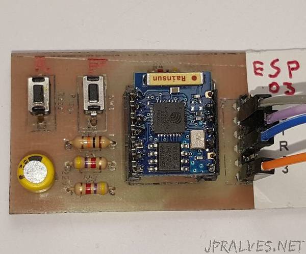
“As everyone knows, the ESP WiFi8266 family, excluding ESP 01, has a 2 mm pitch instead of 2.54 as all standard integrated circuits. This makes it difficult to use them especially if you want to make them movable when replacing or you need to reprogram them. The idea is then to solder the ESP module on female connectors with 2mm pitch that will slip on male connectors, always with 2mm pitch, which in turn will be soldered onto the PCB. This system is particularly useful when booting the firmware, thus preventing the part of communication with the PC where the IDE resides. Once you need to reprogram the module, simply pull it out of your PCB and put it on the programming board. With this Instructable I show you how to build the programming board using the 2mm pitch connectors.”
