
“Interrupts have been an important part of computers since the mid-1950s,1 providing a mechanism to interrupt a program’s execution. Interrupts allows the computer to handle time-critical tasks such as I/O device operations. In this blog post, I look at the interrupt features in the Intel 8086 (1978) and how they are implemented in silicon, a combination of interesting circuitry and microcode.
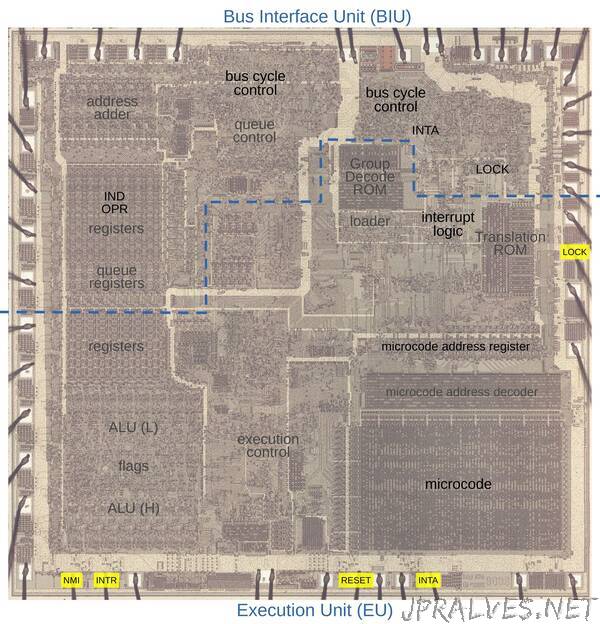
I’ve been reverse-engineering the 8086 starting with the silicon die. The die photo below shows the chip under a microscope. The metal layer on top of the chip is visible, with the silicon and polysilicon mostly hidden underneath. Around the edges of the die, bond wires connect pads to the chip’s 40 external pins; relevant pins are marked in yellow. I’ve labeled the key functional blocks; the ones that are important to this discussion are darker and will be discussed in detail below. Architecturally, the chip is partitioned into a Bus Interface Unit (BIU) at the top and an Execution Unit (EU) below. The BIU handles bus activity, while the Execution Unit (EU) executes instructions and microcode. Both parts are extensively involved in interrupt handling.
Interrupts in the 8086
The idea behind an interrupt is to stop the current flow of execution, run an interrupt handler to perform a task, and then continue execution where it left off. An interrupt is like a subroutine call in some ways; it pushes the current segment register and program counter on the stack and continues at a new address. However, there are a few important differences. First, the address of the interrupt handler is obtained indirectly, through an interrupt vector table. Interrupts are numbered 0 through 255, and each interrupt has an entry in the vector table that gives the address of the code to handle the interrupt. Second, an interrupt pushes the processor flags to the stack, so they can be restored after the interrupt. Finally, an interrupt clears the interrupt and trap flags, blocking more interrupts while handling the interrupt.
The 8086 provides several types of interrupts, some generated by hardware and some generated by software. For hardware interrupts, the INTR pin on the chip generates a maskable interrupt when activated, while the NMI pin on the chip generates a higher-priority non-maskable interrupt.2 Typically, most interrupts use the INTR pin, signaling things such as a timer, keyboard request, real-time clock, or a disk needing service. The NMI interrupt is designed for things such as parity error or an impending power failure, which are so critical they can’t be delayed. The 8086 also has a RESET pin that resets the CPU. Although not technically an interrupt, the RESET action has many features in common with interrupts, so I’ll discuss it here.
On the software side, the 8086 has multiple types of interrupts generated by different instructions. The INT n instruction creates an interrupt of the specified type (0 to 255). These software interrupts were used in the IBM PC to execute a function in the BIOS, the layer underneath the operating system. These functions could be everything from a floppy disk operation to accessing the printer. The one-byte INT 3 instruction creates a breakpoint interrupt for debugging. The divide instructions generate an interrupt if a divide-by-zero or overflow occurs. The INTO instruction (Interrupt if Overflow) generates an interrupt if the overflow flag is set. To support single-step mode in debuggers, the Trap flag generate an interrupt on every instruction.
The diagram below shows how the vector table is implemented. Each of the 256 interrupt types has an entry holding the address of the interrupt handler (the code segment value and the instruction pointer (program counter) value). In the next section, I’ll show below how the microcode loads the vector from the table and switches execution to that interrupt handler.”