
“The 8086 microprocessor was a groundbreaking processor introduced by Intel in 1978. It led to the x86 architecture that still dominates desktop and server computing. The 8086 chip uses microcode internally to implement its instruction set. I’ve been reverse-engineering the 8086 from die photos and this blog post discusses how the chip’s microcode engine operated. I’m not going to discuss the contents of the microcode or how the microcode controls the rest of the processor here. Instead, I’ll look at how the 8086 decides what microcode to run, steps through the microcode, handles jumps and calls inside the microcode, and physically stores the microcode. It was a challenge to fit the microcode onto the chip with 1978 technology, so Intel used many optimization techniques to reduce the size of the microcode.
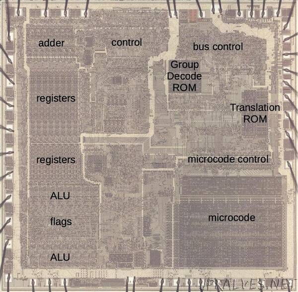
In brief, the microcode in the 8086 consists of 512 micro-instructions, each 21 bits wide. The microcode engine has a 13-bit register that steps through the microcode, along with a 13-bit subroutine register to store the return address for microcode subroutine calls. The microcode engine is assisted by two smaller ROMs: the “Group Decode ROM” to categorize machine instructions, and the “Translation ROM” to branch to microcode subroutines for address calculation and other roles. Physically, the microcode is stored in a 128×84 array. It has a special address decoder that optimizes the storage. The microcode circuitry is visible in the die photo below.
What is microcode?
Machine instructions are generally considered the basic steps that a computer performs. However, each instruction usually requires multiple operations inside the processor. For instance, an ADD instruction may involve computing the memory address, accessing the value, moving the value to the Arithmetic-Logic Unit (ALU), computing the sum, and storing the result in a register. One of the hardest parts of computer design is creating the control logic that signals the appropriate parts of the processor for each step of an instruction. The straightforward approach is to build a circuit from flip-flops and gates that moves through the various steps and generates the control signals. However, this circuitry is complicated and error-prone.
In 1951, Maurice Wilkes came up with the idea of microcode: instead of building the control circuitry from complex logic gates, the control logic could be replaced with another layer of code (i. e. microcode) stored in a special memory called a control store. To execute a machine instruction, the computer internally executes several simpler micro-instructions, specified by the microcode. In other words, microcode forms another layer between the machine instructions and the hardware. The main advantage of microcode is that it turns the processor’s control logic into a programming task instead of a difficult logic design task. Microcode also permits complex instructions and a large instruction set to be implemented without making the processor more complex (apart from the size of the microcode). Finally, it is generally easier to fix a bug in microcode than in circuit logic.
Early computers didn’t use microcode, largely due to the lack of good storage technologies to hold the microcode. This changed in the 1960s; for example IBM made extensive use of microcode in the System/360 (1964). (I’ve written about that here.) But early microprocessors didn’t use microcode, returning to hard-coded control logic with logic gates. This logic was generally more compact and ran faster than microcode, since the circuitry could be optimized. Since space was at a premium in early microprocessors and the instruction sets were relatively simple, this tradeoff made sense. But as microprocessor instruction sets became complex and transistors became cheaper, microcode became appealing. This led to the use of microcode in the Intel 8086 (1978) and 8088 (1979) and Motorola 68000 (1979), for instance.
The 8086’s microcode
The 8086’s microcode is much simpler than in most processors, but it’s still fairly complex. The code below is the microcode routine from the 8086 for a routine called “CORD”, part of integer division, consisting of 16 micro-instructions. I’m not going to explain how this microcode works in detail, but I want to give a flavor of it. Each line has an address on the left (blue) and the micro-instruction on the right (yellow), specifying the low-level actions during one time step (i.e. clock cycle). Each micro-instruction performs a move, transferring data from a source register (S) to a destination register (D). (The source Σ indicates the ALU output.) For parallelism, the micro-instruction performs an operation or two at the same time as the move. This operation is specified by the “a” and “b” fields; their meanings depend on the type field. For instance, type 1 indicates an ALU instruction such as subtract (SUBT) or left-rotate through carry (LRCY). Type 4 selects two general operations such as “RTN” which returns from a microcode subroutine. Type 0 indicates a jump operation; “UNC 10” is an unconditional jump to line 10 while “CY 13” jumps to line 13 if the carry flag is set. Finally, the “F” field indicates if the condition code flags should be updated. The key points are that the micro-instructions are simple and execute in one clock cycle, they can perform multiple operations in parallel to maximize performance, and they include control-flow operations such as conditional jumps and subroutines.”