
“What is a phase-locked loop (PLL)?
A phase-locked loop (PLL) is an electronic circuit with a voltage or voltage-driven oscillator that constantly adjusts to match the frequency of an input signal. PLLs are used to generate, stabilize, modulate, demodulate, filter or recover a signal from a “noisy” communications channel where data has been interrupted.
PLLs are widely used in wireless or radio frequency (RF) applications, including Wi-Fi routers, broadcast radios, walkie-talkie radios, televisions and mobile phones.
At its simplest, a phase-locked loop is a closed-loop feedback control circuit that’s both frequency- and phase-sensitive. A PLL is not a single component, but a system that consists of both analog and digital components — interconnected in a “negative feedback” configuration. Consider it analogous to an elaborate operational amp (op amp)-based amplifier circuit.
What is a phase-locked loop used for?
The main goal of a PLL is to synchronize the output oscillator signal with a reference signal. Even if the two signals have the same frequency, their peaks and troughs may not occur in the same place. Simply put, they do not reach the same point on the waveform at the same time.
Known as the phase difference, this is measured as the angle between the signals. For signals with varying frequencies, the phase difference between them will always vary, which means that one signal will lag or lead the other by a varying amount.
A PLL reduces phase errors between output and input frequencies. When the phase difference between these signals is zero, the system is said to be “locked.” And this locking action depends on the PLL’s ability to provide negative feedback — i.e., route the output signal back to the phase detector.
In addition to synchronizing the output and input frequencies, a PLL also helps establish the input-output phase relationship to generate the appropriate control voltage. Therefore, it helps achieve both frequency and phase lock in a circuit.
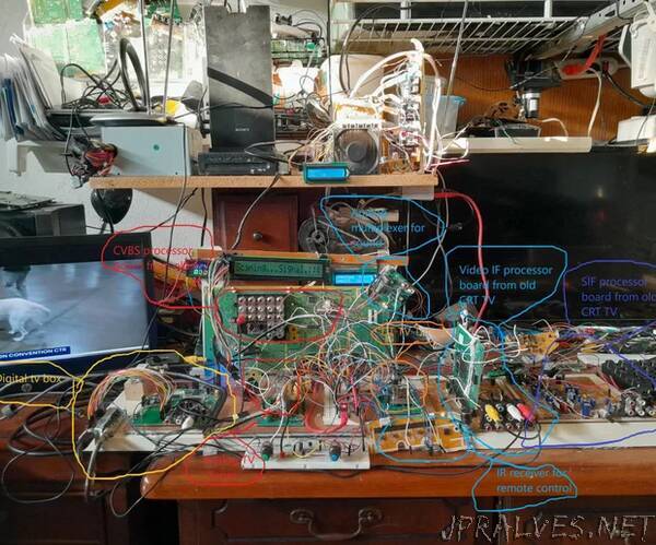
2.in this project I did use three different TV tuner
1.The SN761662 is a low-phase-noise synthesized tuner IC designed for digital TV tuning systems. The circuit consists of a PLL synthesizer, three-band local oscillator and mixer, 30-V output tuning amplifier, four NPN band-switch drivers, and is available in a small-outline package. A 15-bit programmable counter and reference divider are controlled by I2C bus protocol. Tuning step frequency is selectable by this reference divider ratio for a crystal oscillator.
2.The TDA6508A This device is a programmable 3-band mixer oscillator and synthesizer intended for LOW, MID and HIGH band TV and VCR tuners. It has three double balanced mixers and three oscillators for the LOW, MID and HIGH band respectively, a PLL synthesizer, and an IF amplifier.
3.The TUA 6039F-2, TUA 6037F device combines a mixer-oscillator function and an IF AGC amplifier with a digitally programmable phase locked loop (PLL) for use in analog and digital terrestrial applications.
Supplies:
1.SN761662 DTV Tuner consist of a PLL synthesizer, three-band local oscillator and mixer with a digitally programmable phase locked loop (PLL) for digital tv tuning systems.
2.TDA6508A 3-band mixer/oscillator and synthesizer with a digitally programmable phase locked loop (PLL) for terrestrial tuners.
3.The TUA 6039F-2, device combines a mixer-oscillator function and an IF AGC amplifier with a digitally programmable phase locked loop (PLL) for use in analog and digital terrestrial applications.”