
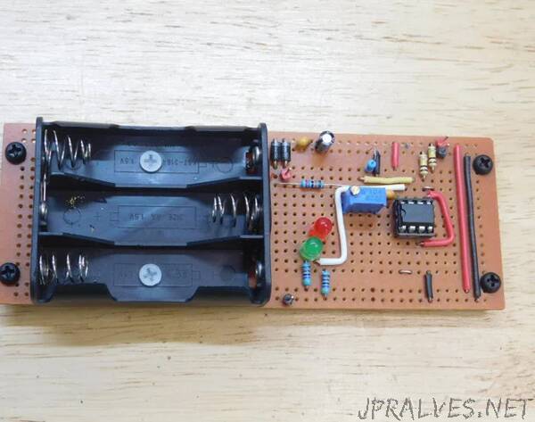
“This is not a battery charging circuit, just a basic circuit for brief interruptions in mains power. This circuit monitors the battery level and will indicate if the batteries are good with a green LED, and when they should be replaced with a red LED. With Schottky diodes, there is no interruption in power when mains power supply removed (power outage) or simply unplugged so you can move your project without a power drop.
For where I live, brief power outages are common and I needed something for a binary clock I built as well as a digital clock I am working on. I came across this circuit on a digital clock schematic, redrew it to correct some errors, and it works great. I have this operational in 3 projects I have made.
Supplies
- Full size breadboard or solderable breadboard, x1
- 3 cell AA battery holder, x1
- AA battery, x3
- IC TL072, x1
- 8 pin socket, x1
- header pins, x4
- diode 1N5819, x2
- LED, green, 5mm, x1
- LED, red, 5mm, x1
- resistor, 100K trim pot (104, 3296W), x1
- resistor, 100K, x2
- resistor, 470K, x1
- resistor, 270K, x1
- resistor, 4.7K, x2
- 10 μF 25 volt electrolyte capacitor, x1
- 100 nF (104) monolithic capacitor, x2
- If making this on a solderable breadboard, I used the following parts for mounting the battery holder and the PCB:
- hex nylon standoff, M3x6, x6
- nylon pan head screw, M3x4, x4
- nylon countersunk screw, M3x10, x2”