
“Designed to Work with Signals up to 2 MHz, it should work with your Arduino Oscilloscope
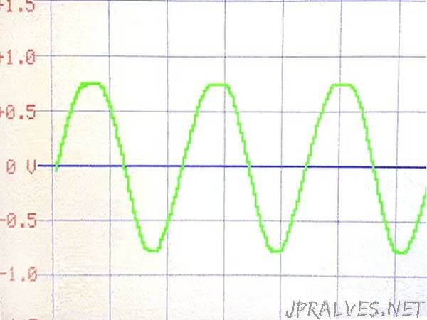
In a recent posting, I presented a 2 MHz oscilloscope using the Arduino Giga. I used a very simple arrangement to scale and condition the incoming signal.
I mentioned at the time that the right way to do this was probably to use op amps to properly condition the signal, allowing for a range of signal amplitudes, etc. while protecting the ADCs from high voltage. This project is about doing a signal conditioner a better way. My intent here is to present a signal conditioner that should work with any Arduino oscilloscope. And I want to experiment with auto-scaling- i.e. let the processor scale the signal and set the vertical scale on the display.
I have to admit that this project quickly got me way out of my comfort zone and into areas where I have very limited knowledge and experience. I’m an Arduino guy, and this is basically RF analog! The design took many hours of experimentation to find the right parts and the right circuits. I have come up with something that works, but it could be improved. I will talk later about performance and how well this project succeeded in meeting its objectives. I learned a lot during the design and construction of this project and will attempt to share what I learned in this project tutorial.
What do we want our Signal Conditioner to do?
1. We want to be able to handle a wide range of signal amplitudes and voltages and protect the ADC from damage.
2. We need to scale the signal to 0 - 3.2 volts and center it at +1.6 volts for a 3 volt processor (or 0-5 volts centered at +2.5 volts for a 5 volt processor).
3. We want this scaling process to amplify low voltage signals and attenuate high voltage signals. We also would like all this to happen automatically under our processor’s control.
4. We want it to work with signals up to at least 2 MHz.”