
“If 100 people lived on Earth, 74 had drinking water available when needed and free of contamination. (source: who). With this instructable, slightly more.
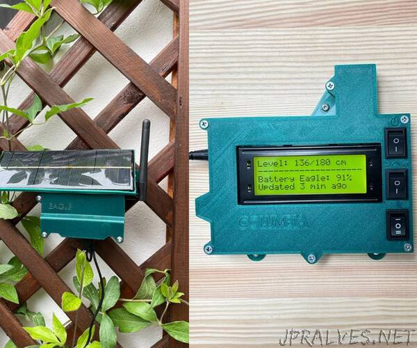
The equipment presented here permanently monitors and controls the water supply for a community of 7 houses. Hang around, I’ll explain everything.
For five decades a small community in eastern Europe, in northern Romania, is dependent on a natural uphill spring water source; since the harmony with nature is declining ever since, a second source of water has been found - a well, which however requires an additional pump that fills the main supply tank.
The constant monitoring and pump control, which so far were done manually, is now automatic. This is a massive improvement, since monitoring the water level is critical for two reasons:
It is highly inconvenient to remain out of the blue without running water
Since an empty tank means air in the water lines, purging the system takes days to function again fully normally
An in-depth analysis of the equipment will be done in the step “Architecture”.
Equipment:
PC with Atmel Studio for C-code and UltimakerCura for 3D printing preparation
3D printer (I use Creality Ender)
Screwdrivers, pliers
Soldering gun
patience, coffee or tee
Components: I bought most of the parts on Ebay Germany, but for an international reach I was looking up the same components on Aliexpress.
So there you go:
- PCB: 1 for Master, 1 for Slave - see step “Circuitry and PCB Ordering / Preparation”
- Arduino nano: 2x
- Charging module TP4056: 1x
- Solar panel: 1x
- Radio module for master NRF24l01: 1x
- Radio module for slave NRF24L01+PA+LNA: 1x
- LCD display 20x4: 1x
- Ultrasonic sensor AJ-SR04M: 1x
- Boost converter MT3608: 1x
- Battery for Slave: I’ve used a 6000 mAh battery (65mm x 57mm x 9mm), which is much more than enough (without charging it lasts over 3 weeks of continuous operation). I’ve had it around and used it, but you can definitely use a smaller one - the solar panel is charging it all the time. Currently, I cannot find any identical one online.
- Resistors: 10kOhm, 100Ohm, 330Ohm, 220Ohm -> see Gerber files
- Capacitors: 100nF (4x), 10uF (7x), 100uF (2x) -> see Gerber files
- Linear voltage regulators: 1xLD1117v50 and 2xLD1117v33. At the time of order, I didn’t find any LD1117v50 that comes within a reasonable amount of time, so I adapted an AMS1117 instead.
- Diode 1N4148: 1x
- Connectors on PCB: JST PH cable: 2x
- LEDs (1 x red, 1 x green and 1 x RGB); since the RGB is intended only for initialization status/diagnostics, I used a simple LED instead.
- DC Jack Barrel 5.5x2.1 mm for the power input
- Relay for pump switching: SONGLE PCB 5V: 1x
- Mini-switches: 2 pins - 3x, 3 pins - 1x
- Transistors BS170: 2x
- Screw terminal blocks for connecting the switches to the PCB
- Screws for fixing the boards in the casings (I used locally found screws from DIY markets: M2.5x10) and screws for fixing together the casings: 3x10mm (ebay)
- Power supply for Master: 1x. You basically can use any power supply with an output Jack terminal 5.5x2.1mm and a maximum voltage of 15V.
(Optional) 16mm in diameter flexible cable tube to protect the sensor cable”