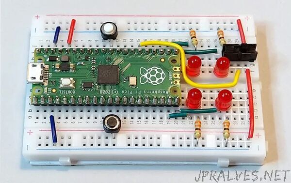
“This project is adapted from the staggeringly popular Make: Electronics Third Edition, which has been completely re-re-written with most photos and schematics replaced and updated!
During 2021 I started writing a third edition of my book Make: Electronics. One of the pleasures of this task was that I could rethink all the circuits, and with the benefit of hindsight, I saw how to simplify one project in particular: The intrusion alarm.
You’d think an alarm should be easy enough. Just place some sensors on doors and windows, wire them to a beeper, and — job done!
But it’s not so simple. First, the alarm has to notify you that all the doors and windows are closed before you activate it. Then you need a delay (which I call the Exit Delay) so that you can leave the area without causing the alarm to start making a noise. When you come back, you need another delay (which I call the Last Chance Delay) to prevent the alarm from beeping or wailing till you have a last chance to switch it off. The diagram below shows what I mean.
The word delay suggests a component that measures time. That could be a timer, couldn’t it? In fact you can build this circuit entirely with three 555 timers — the old-school chips that have outsold all other chips ever made. Along the way you’ll learn about pullup and pulldown resistors, diodes, and coupling capacitors, which can be useful in many other applications.
IC1, IC2, and IC3 are acronyms for integrated circuits, which are the three 555 timers.
Materials
- Resistors: 470Ω (4), 10kΩ (5), 47kΩ (4), and 470kΩ (2)
- Capacitors: 0.01µF (2), 0.47µF (2), 10µF (3), and 100µF (2)
- LEDs (4)
- 555 timer ICs (3)
- 1N4148 diode (1)
- Tactile switch (1)
- SPDT or DPDT switch (1)
- 9V battery and battery clip with leads
- Solderless breadboard
- Raspberry Pi Pico microcontroller (optional)”
