
“The project is about the design of a digital tachometer, a device used in the measurement of speeds of rotating bodies.
Story
A tachometer is a gadget that is used in the measurement of angular speeds of bodies, more so bodies in rotary motion example is the shaft of a motor. The units used by the tachometer are rev/min, ft/min, or m/sec. The tachometer is also used in the measurement of distance or length. Here the units used are meters, yards, or feet. An example of a tachometer is the car speedometer.
In this article, am going to introduce the Handheld Digital Tachometer and which finds common use in the industry during the measurement of rotating motor shaft and fans speeds.
- This is a handheld portable device that can be operated as non-contact through its laser pointer or as contact via its nozzle.
- This means you can use the tachometer as contact or non-contact depending on how you want to measure the speed of a rotating body conveniently.
The Schematic
I build the schematic through KiCAD EDA. The schematic was built around a 555 timer, 7811 IC, 4069, 4081, and CD4059 ICs. The schematic was a sensitive one that could measure the speed of rotation and display it on the seven-segment as voltage. Below is the schematic
The PCB Layout
The schematic was passed through the annotation process, loaded with footprints and the electrical design rule check was done all successfully. The generation of the BOM and the Netlist was done then the schematic was pushed to the PCB layout window. Here the PCB routing was done where each component was interconnected with traces. The edge cut was added to give the PCB a border edge. Again we had to add vias and copper pores to our board. t is at this level again where we added the names and labels on our board.
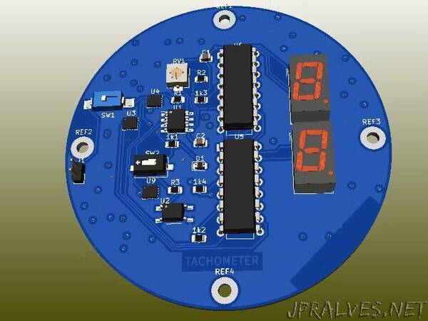
PCB 3D generation
From the PCB layout, the PCB is converted to the 3D view which represents how the PCB will appear after manufacturing. This is still done within KiCAD by pressing view, the 3D view and the board attached below will appear.
Generation of the Manufacturing files
This is the most critical part and we need to do it very nicely because it is the one that determines what our manufactured board will look like. Download Geber files, BOM, drill files, and pick and place files then share with them to manufacturers to start the process.”