
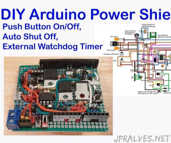
“An Arduino shield is a circuit board with electrical components already permanently set up. This board is then plugged right into an Arduino board, making all the connections of the components fast and convenient, and error free. You can buy ready-made ones, but this one I made with discrete components soldered on a perf board. I designed it to add on to other Arduino projects, so it has many, many connection options, with the following features:
- Pushbutton to power on
- Programable pushbutton to shut off
- Programable auto shutoff
- External watchdog timer to reset the Arduino if it freezes
- Optional ATtiny85 to control these functions, freeing the Arduino’s resources to handle other tasks
Reason for starting this shield: In a data logging project with a battery-operated Arduino, I was recording to a microSD card. When I went to retrieve the data, the file was corrupted and all of my data was lost. This actually happened multiple times. I eventually figured out that that when the battery died the microSD card reader must have been recording to the card and so the file was not closed, and thus not saved. So, I decided to make an Arduino shield that would allow the Arduino to monitor the battery voltage and stop trying to save data when the battery started getting too low. Since I was going to the trouble of making a shield, I decided to add other features.
Background resources: The ideas for this project are a compilation of different sources I found on the internet. Please look them up if you want more information. Indrek Luuk wrote an article on a website called circuitjounal.com regarding the auto shutoff circuit for the Arduino. Ralph Bacon also made a YouTube video on an auto shutoff circuit, but currently he always uses a dedicated chip (SI4599) which has the dual MOSFETs like the circuit described here. Ralph also discussed the external watchdog timer circuit on YouTube, but he based that on an article written by Wolfgang Borst which is published on the internet in ElektorMagazine.
In this Instructable I present the Fritzing image of the circuitry of my DIY power shield, some example code and video demonstrations. Since much of it is explained in the above-mentioned sources, I will not repeat the finer details of how the electronics work, but if you have questions for me, feel free to leave them in the comment section at the end. I include a couple of videos showing the pushbutton/auto shutoff and 555 timer setups on a breadboard to demonstrate them working separately from the shield.
Supplies:
General Components for the shield
- 6cm x 8cm perf board
- Screw terminal
- Two switches (SPDT)
- AMS 1117 5Volt voltage regulator
- 3-pin 90-degree male header pins (to solder to the pins of the AMS 1117)
- Two 10uF tantalum capacitors (for the AMS 1117)
- One micro-USB port (remove the data pins)
- Female header pins (3-pin, 6-pin, two 8-pin, 10-pin)
- Male header pins (ideally various colours, I used a total of 63, some pairs, triplets, etc.)
- Two 10 kOhm resistors
- Lots of jumper wires
- Jumper connectors (about 10, to connect adjacent male header pins)
Components for the pushbutton ON/OFF circuit
- Logic-level N-channel MOSFET (I used FQP30N0 6L)
- Logic-level P-channel MOSFET (I used IRF9630)
- Momentary pushbutton
- two diodes (I used Schottky diodes, both regular rectifier diodes should work)
- 10 kOhm resistor
- 100 Ohm resistor
- 47 kOhm resistor
Components for External Watchdog Timer
- 555 timer IC
- 8-pin IC socket
- One 1 MOhm (for 555)
- Two 200 kOhm (or 400 kOhm, for 555)
- One 10 uF electrolytic capacitor
- Two 100 nF ceramic capacitors
- One 10 nF ceramic capacitor
- Logic-level N-channel MOSFET (FQP30N0 6L)
- Rectifier diode
- 10 kOhm resistor
- 27 kOhm resistor
Components for the Optional ATtiny85
- ATtiny85
- 8-pin IC socket
- 10 kOhm (optional pull up for reset pin)
Tools: Soldering iron, needle nose pliers, X-acto knife and file if you want to trim the edge of the shield, multimeter, etc.”