
“There’s a lot of arduino/ESP32 clocks going around, but do they use those nice and crisp OLEDs?
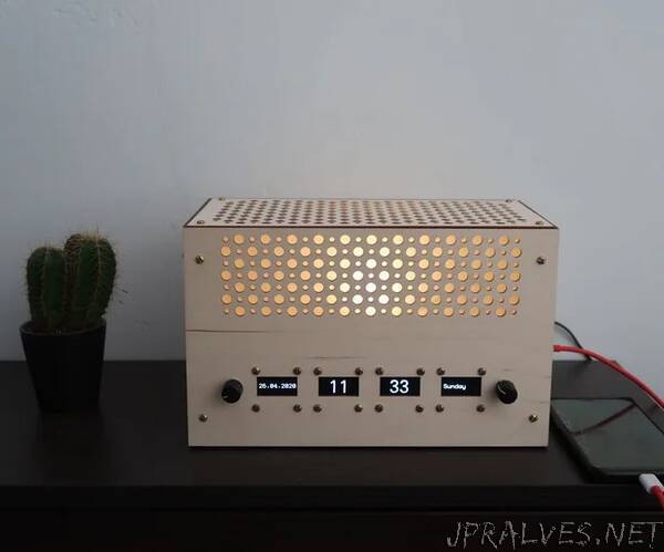
I’ve been experimenting with arduinos and ESP32’s for a while now, but I never made it to a finished product. I’ve made an alarm clock with 4 1.3 inch monochrome OLEDs. The clock also features a dimmable bedside lamp and an USB charging port (no one has spare outlets next to his bed). The OLEDs are dimmable as well, this was added last minute after my project was threatened by my girlfriend. Should dim not be -in girlfriends voice- dim enough, I can also provide a version of the code where 3 displays are powered of between certain hours. The goal was to make an easy serviceable clock, with a look beyond “prototype”. While making my clock I encountered some difficulties I had to solve, which is why I think this instructable is worth sharing. The clock can be made with little tools, I don’t like the “and for the next step I used my 10.000/$ CNC mill” tutorials.
Some things that will be explained in this instructable (in-structable-ception):
- How to use/wire an I2C OLED display with arduino/ESP32
- How to use multiple I2C objects with one arduino/ESP32
- How to make a “scroll-able” menu using a rotary encoder (+ how to use an encoder with an ESP32/arduino)
- How to design and order a custom PCB using fritzing.
- The clock also uses a RTC (real time clock), led driver, step down voltage module… I won’t really get in to these because there’s really a lot of information readily available for these modules.
I would like to note that I’m not a professional programmer. The goal of my instructable is to explain the points I mentioned above. How I put it all together for my final product is might not be the cleanest way. It’s the way that allowed me to keep track of it all.
Supplies:When shopping for supplies I always try to weigh for the importance of quality/documentation vs price. My supplies are a mix of A-brands and cheaper Chinese parts. Mouser is a great supplier if quality is important, I order from Banggood/Aliexpress for the cheaper parts.
- An ESP32 board, I used the Huzzah32 from adafruit, but there are lots of other (cheaper) options. I chose the Huzzah32 because it’s very well documented.
- 4 1.3 inch I2C OLED displays (128x64, with the SH1106 driver), the 0.96” ones are more common but for this project I prefer the 1.3” ones
- Sparkfun femtobuck driver to drive the LED
- RTC clock, I used one with a lithium cell
- Arduino nano
- Female USB 2.0 port (I used: SS-52200-002 from Stewart Connector)
- Female DC jack (I used: L722A from Switchcraft)
- 12V 3A DC adapter (GST36E12-P1J from Mean Well)
- Custom PCB, optional but this makes the project a lot more compact and easily serviceable if a part dies + more reliability because less wires (jlcpcb.com)
- M3 screws & bolts
- M3 brass inserts
- 12V to 5V step down module from Pololu (DF24V22F5)
- 3 watts powerled with heatsink
- Jumper wires
- Buzzer
- I2C multiplexer (TCA9548A from adafruit)
- 2 Rotary encoders (I’ve tried some, not all work with my code. The one from “DFrobot” works and so does the one from with the round PCB from “DIYmore”. My code doesn’t seem work for the pushbutton of the KY-040 type.My alarm clock uses the one from DIYmore because they are very easy to panel mount (no extra screws/holes needed).
- Assortment of female headers (optional)
- Wood for the frame: 18mmx18mmx2400mm
- Tracing paper
I used some tools (soldering iron, 3rd hand, saw…) as well, but nothing really exotic.”