
“The ESP32s, are a series of inexpensive microcontrollers, introduced in the last quarter of 2016. They are powerful systems on a chip (SoC) and can replace the ESP2866, and perhaps one might say even the Arduino UNO. Athough, clearly they are much more complex to use.
An ESP32 development board contains a 32-bit Tensilica Xtensa LX6 chip, with both dual-core or single-core options available now (and perhaps more options available in the future). They are made using 40 nm fabrications.
These chips have PWM, ADC, and DAC capabilities, as well as I2C, SPI, UART, Standard Bluetooth, Bluetooth Low Energy, CAN 2.0, and 2.4 Ghz WiFi interfaces.
In general, ESP32 development board GPIO pins 6 through 11 should normally be left unassigned in your project.
One of the complexities of an ESP32 development module is that each pin, on a typical development board, has multiple functions. That is, each pin is multiplexed. This is unlike the Arduino UNO, were we have primarily two types of header pins: digital and analog.
The ESP32 has a faster processor than the ESP8266 or the Arduino UNO. It runs at 160 Mhz, compared to a default speed of 80 MHZ for the ESP8266, and only 16 MHz for the Arduino UNO.
Since we can use the same graphical user interface (GUI) for both, an Arduino UNO board can provide a a gentle entry point before turning to the ESP32 development module. Capability is only enhanced when one finally uses the ESP32 development module, after using the Arduino UNO.
The ESP32 has some built-in sensors that we normally might find ourselves adding to an Arduino UNO. There are sensors on the ESP32 for touch, the Hall effect, and temperature (although this is for the chip’s internal temperature and not ambient temperature).
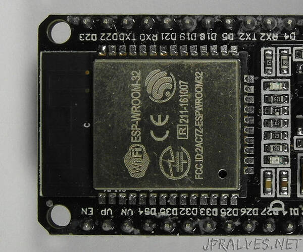
Typically an ESP32 development board has 30 or 36 six pins spread evenly over two sides. These pins represent a transfer of functionality from the chip. An ESP32 development board contains an ESP32-WROOM-32 chip, made by Espressif Systems.
The ‘W’ in the name is silent. So, ‘WROOM’ is pronounced as ‘room’.
The ESP32-WROOM-32 chips were on the boards that were the first publicly available.
We will look at two categories of sensors (touch and Hall effect) included on the chip, and use them in turn, in this tutorial. This tutorial will also cover the I2C and PWM capabilities built-in to ESP32 chips, and consequently most ESP32 development boards.
In what follows we will use the “DOIT” ESP32 board; these are relatively inexpensive, although there are a multitude of ESP32 development boards to choose from. Fortunately, almost all ESP32 development boards can use all, or most, of the functionality discussed below.
The maximum current through any pin on an ESP32 chip apparently should not exceed 12ma with 6ma recommended, although there seems to be some confusion on this, with some web pages suggesting 40ma.
A useful point I found is that when my development board is run from a five (5) volt USB source, I get five (5) volts out of the VIN pin, the pin on the bottom left, if the board is facing upward, and the USB connector is toward the bottom of the board. I use this information to power any I2C device that requirea 5 volts, e.g, 2004s or 1602 I2C displays.
I will use this feature below when I discuss my board’s, and other ESP32 boards, built-in capabilities to use I2C.
The ESP32 has a lot going for it, however, it is not without any problems. Most issues can, fortunately, be traced to unstable power. This is something you should check, preferably with a storage oscilloscope, if you are having any difficulties.
Supplies:
The required items are;
- An ESP32 development board (here we use the “DOIT” ESP32 development board)
- Four (4) F-F Dupont Wires
- One (1) M-F Dupont Wire
- Two (2) M-M Dupont Wires
- A magnet (any kind will do, but one with a strong field is best)
- An I2C 1602 LCD display (a piggyback I2C adapter is used here to obtain an I2C LCD)
- An LED of any color (10mm is used here), but a 5mm or 3mm will work as well
- 330 Ohm resistor (or a resister greater than this to limit current to the LED)
- An optional breadboard, which should prove useful when we look at PWM.
The two (2) M-M Dupont wires, the LED, the I2C 1602 display, the resistor, as well as the optional breadboard are only used for the Step on PWM.”