
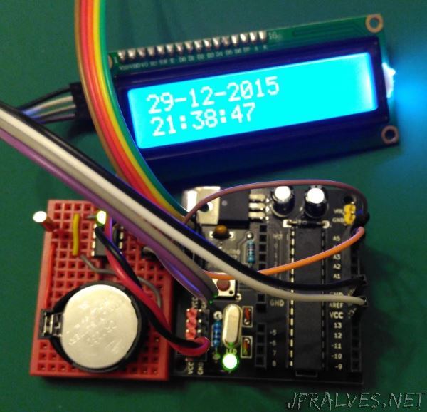
Being near the end of the year, we decided to build a circuit to control a Real Time Clock (RTC). An RTC is characterized by being an autonomous time source that works independently from the rest of the circuit. To implement this circuit we used the DS1307, this IC communicates with the outside through the I2C protocol.
A CSEduino was used to program the time and to display it later.
The DS1307 needs an oscillator crystal (32.768 KHz) and a 3.3V backup power supply (typically a CR-type battery) for when the IC is not powered.
The I2C communication is done through the IC’s two pins SCA and SCL (these must have resistors connected to the 5V to ensure that they have a Pull-UP on the lines. This is because the IC has transistors that operate in open-drain mode.
The DS1307 has a 56-byte NVSRAM memory. This has fixed positions where the current date/time is located:
- Address 00h - Seconds (uses bits 0-6) and is stored in BCD format (Bit 0-3 for the units (0-9), bit 4-6 for the tens (0-5)). Bit 7 is used for CH - Clock Halt - allows you to stop the clock.
- Address 01h - Minutes (uses bits 0-6) and is stored in BCD format (Bit 0-3 for the units (0-9), bit 4-6 for the tens (0-5))
- Address 02h - Hours
- Bit 6 to indicate whether it is 12 or 24.
- In 24-hour mode - bit 4-5 for the tens (0-2)
- In 12-hour mode - bit 4 for tens (0 or 1) and bit 5 for AM or PM.
- Bit 0-3 - for the units (0-9)
- Address 03h - Day of the week (uses bits 0-3) (0-7)
- Address 04h - Day of the month (uses bits 0-5) and is stored in BCD format (Bit 0-3 for units (0-9), bit 4-5 for tens (0-3))
- Address 05h - Month (uses bits 0-4) and is stored in BCD format (Bit 0-3 for the units (0-9), bit 4 for the tens (0-1))
- Address 06h - Day of the month (uses bits 0-7) and is stored in BCD format (Bit 0-3 for the units (0-9), bit 4-7 for the tens
(0-9)) - Address 07h - Bit 7: OUT, Bit 4: SQWE, Bit 1: RS1 and Bit 0: RS0. This address is used to control the operation of the SQW/OUT pin.
- Address 08h to 3Fh - RAM
Schematic
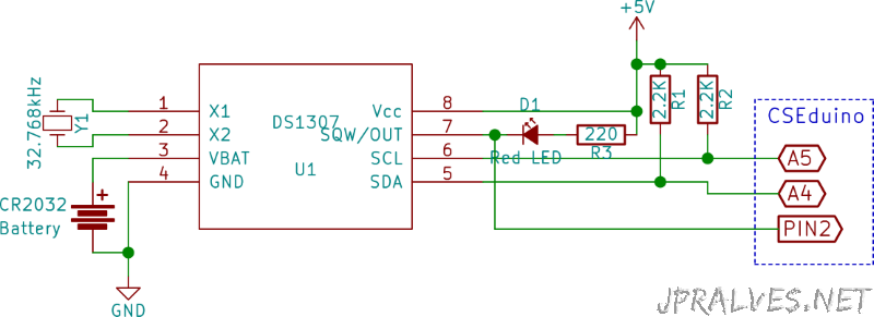
Bill of materials (BOM)
- 1x IC DS1307 (U1)
- 1x LED 5mm Red (D1)
- 1x 220 Ohms Resistor (R3)
- 2x Resistors 2.2K Ohms (R1, R2)
- 1x 32.768kHz Oscillator Crystal (Y1)
- 1x 3.3V Battery - CR2032
We associated to the project a display LCD with the integrated HD44780 (see the LCD circuit) to show the date. The CSEduino (see additional information on page) was added to write and read the RTC information and show it on the Display LCD.
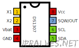
IC/Components Pin-out
Code
The sketch should be loaded into an Arduino through its IDE (version 1.6.6 was used).
The following code uses the following external libraries:
- NewliquidCrystal. It can be downloaded locally from this link.
- Time. It can be downloaded locally from this link
- DS1307RTC. It can be downloaded locally from this link
#include <Time.h>
#include <Wire.h>
#include <DS1307RTC.h> //a basic DS1307 library
#include <LiquidCrystal_I2C.h>

// LiquidCrystal_I2C lcd(0x27);  // Set the LCD I2C address

LiquidCrystal_I2C lcd(0x27, 2, 1, 0, 4, 5, 6, 7, 3, POSITIVE);

const int sqw_pin = 2;

void setup() {
  lcd.begin(16, 2);
  lcd.home();
  lcd.print("CSEduino LCD i2C");
  pinMode(sqw_pin, INPUT);
  Serial.begin(9600);
  setSyncProvider(RTC.get); //this is the function to get the time from the RTC
  lcd.setCursor ( 0, 1 );        // go to the next line
  if (timeStatus() != timeSet) {
    lcd.print("Unable to sync");
    delay ( 5000 );
  }  else {
    lcd.print("RTC system OK");
    attachInterrupt(digitalPinToInterrupt(sqw_pin), setDisplay, FALLING);
    RTC.sqwOutput(1);
  }
  lcd.clear();
}

volatile byte display = 1;

void setDisplay() {
  if (display == 0) {
    display = 1;
  }
}

void loop() {
  if (Serial.available()) {
    display = -1;  //disable display updates
    time_t t = processSyncMessage();
    if (t > 0) {
      RTC.set(t); //set the RTC and the system time to the received value setTime(t);
    }
    display = 1;
  }
  if (display > 0) {
    digitalClockDisplay();
    display = 0;
  }
}

void digitalClockDisplay() {
  if (display) {
    //digital clock display of the time
    lcd.home();
    lcd.print(day());
    lcd.print("-");
    lcd.print(month());
    lcd.print("-");
    lcd.print(year());
    lcd.print("  ");
    lcd.setCursor ( 0, 1 );        // go to the next line
    printDigits(hour(), true);
    printDigits(minute(), true);
    printDigits(second(), false);
  }
}
//utility function for digital clock display: prints preceding colon and leading 0
void printDigits(int digits, boolean sep) {

  if (digits < 10)
    lcd.print('0');
  lcd.print(digits);
  if (sep)
    lcd.print(":");
}

//code to process time sync messages from the serial port
#define TIME_MSG_LEN 11 //time sync to PC is HEADER followed by Unit time_t as ten ascii digits
#define TIME_HEADER 'T' //Header tag for serial time sync message

time_t processSyncMessage() {
  //return the time if a valid sync message is received on the serial port
  //time message consists of a header and ten ascii digits
  while (Serial.available() >= TIME_MSG_LEN) {
    char c = Serial.read();
    Serial.print(c);
    if (c == TIME_HEADER) {
      time_t pctime = 0;
      for (int i = 0; i < TIME_MSG_LEN - 1; i++) {
        c = Serial.read();
        if (c >= '0' && c <= '9') {
          pctime = (10 * pctime) + (c - '0'); //convert digits to a number
        }
      }
      return pctime;
    }
  }
  return 0;
}
// Sketch uses 8,970 bytes (27%) of program storage space. Maximum is 32,256 bytes.
// Global variables use 549 bytes (26%) of dynamic memory, leaving 1,499 bytes for local variables. Maximum is 2,048 bytes.
The code needs by an input in the format “T999999999999” via the serial port that will do the Setup of the RTC. The number after the letter “T” should be 10 digits long and represent the number of seconds since January 1, 1970.
To get this number under Linux just run the command: date +%s.
On Windows, to get this number you should create a file with the extension vbs and put in it the following content: wscript.echo(datediff("s",#1970/1/1#,now())).
If both solutions are too complicated you can go to the following link and see the value.
The SQW register is also set so that it pulses at 1Hz, i.e. 1 time per second. This input is connected to pin 2 of the CSEduino that has an interrupt associated with this pin, updating the date on the LCD only when it is the pin’s value goes to 0.