
“Dual Clock System consisting of two Pico-2040 micro controller-based clocks connected via I2C
The Multi-functional Clock System is composed of two distinct clocks, each based on the Pico-2040 micro controller. These clocks are interconnected via an I2C Bus, facilitating communication and synchronization between them. While each clock possesses its own Real-Time Clock (RTC) module, the primary timekeeping function is delegated to the second clock. The first clock features large common-anode seven-segment LED displays, while the second clock employs MAX7219 LED matrix displays for versatile messaging and data presentation.
FUNCTIONALITY:
- Clocks synchronize their RTC modules on power-up, with Clock-1 acting as the master and Clock-2 as the slave.
- Clock-2 manages various subcomponents such as the MP3 player, SD card reader, and sensors, while Clock-1 primarily handles display and user input.
- Time Division Multiplexing is employed in Clock- 1 for efficient display management, with appropriate driver ICs utilized for driving large seven-segment displays.
- Remote control enables convenient access to all clock functions, including time and alarm setting, audio mode selection, volume adjustment, and display control.
KEY FEATURES :
- The Clock consists of 2 different Pico-2040 based clocks connected together using I2C interface. Each clock has its on RTC(cheap DS 1307 RTC modles are used here) which will be synchronized while switching on the power.
- Clock-1 features large seven-segment displays for time indication, while Clock-2 utilizes scrolling LED matrix displays for displaying time, date, temperature, humidity, and messages. I have uses four 2.3 inch common anode Seven segment displays for the display of Hour/Minute and two 1 inch Seven segment Displays for displaying Seconds. The clock’s hard ware is capable of handling even higher sized seven segments if required.
- Clock-2 has a MAX7219 scrolling LED matrix Display for display of Time, Date, Temperature, Humidity, time based wishing like Good morning, Good night etc and other status messages when come over in different modes. This display also used to read and display the text files stored in SD card line by line.
- A mini MP3 player is integrated with the clock, using which any music can be played as Hour chime, Alarm, and also for playing any music(such as prayer songs) at any prefixed time. Also the clock can speak out the time, using this MP3 player. Though it can set to speak any time, the clock is here set to speak out at every half hour. On each full hour it is set to play a chime.
- An Ultra sound sensor is integrated with the second clock which will sense some one comes near it and play randomly stored words like ( hi, hello.. how are U etc), and also display the same in words on the message board. Hundreds of such audio /words can be stored on the SD cards to select and display at random.
- A DHT 11 module is integrated with the second clock for reading the room Temperature / Humidity and display these on it’s moving display.
- A Full function remote is integrated for accessing all functions of the clock. Clock 1 is provided with an IR sensor, which can be accessed with a standard remote control. Real time, Alarm time, Date /year, different audio modes, volume of music player, etc can be set using the remote control. The Chime/Ultra sound sensor can be fully muted, fully activated or muted at night only by setting the remote control appropriately. Alarm also can be permanently muted or activated. Stopping of Alarm / audio playing can also be done using the remote.
- The Led matrix display continuously scroll out real time, date, temperature, humidity, time based wishing( like Good morning, Good Night etc..) normally. While playing the music( here I set the clock to play 2 prayer songs one at 6.10 am and other at 6.10 pm) the display read and play the lyrics of the prayer line by line from the SD card and display it while playing the prayer on MP3 player. The LED matrix also displays status messages each time when a key is pressed on the remote control like “Set time”, “Set Alarm “, “Set Date”, “Set Volume”, “Alarm off ” etc. Alarm time and other settings of the clock will be written on the SD card itself on a specific file, and is read out each time when the clock is switched on. This display also compliment with some animations while the clock strikes full hour and half hour.
- SD card reader, MP3 player and Ultra sound sensor are integrated with clock-2. Real time is also being maintained by the second clock. So each time the clock is switched on, the first clock request data from the second clock and the second clock send data consisting of Real time, and other data read from its SD card like Alarm set time, volume, status of chime play, alarm permanently off /on.. etc to the first clock via inter connected I2C bus. The first clock Set its time in synchronization with the data and time received from the second clock.
- For I2C Communication clock 1 act as master clock and clock 2 is in slave mode. Since IR receiver is connected with the first clock, it respond to the Remote control and send the data received from the remote to the second clock via I2C for use and for writing on SD card for future use. It also prompt the second clock to display the status of different setting on its display when a remote control key is pressed.
PROJECT DESCRIPTION:
The clock is built around 2 PICO 2040 micro controllers. The project is divided in to 2 independent clocks which are connected together through I2C Bus. Each clock has its on RTC modules, but real time is maintained by the second clock. The first clock synchronize its RTC with the second clock each time when the clock is switched on. The first clock has big sized common anode seven segment LED displays and the second clock has 3 MAX 7219 LED matrix displays connected serially (4X3=12 units total), which is enough for scrolling messages of long lines. The second clock is mainly used for displaying the messages and maintaining different sub components like MP3 player, SD card reader, Temperature sensor, Ultra sound Sensor etc. Since scrolling messages on a MAX 7219 display is a processor hungry one, it’s a bit difficult to manage all the sub components, though I managed to do with the software. As a fancy thing I have added an ultra sound sensor which will respond to some one coming near the clock and speak and display some random words like Hello, Hai, How R U etc. If required it can be made to speak out real time when some one come near it!
All communication interfaces like I2C, SPI and UART are used in the program for communication with different modules. in fact two different I2C Bus of the processors are used independently one for connecting RTC with the processor and other for inter processor communication. Although one I2C bus can be used for both the purpose, due to some conflicts encountered I used different I2C busses for each purpose.
One Single 12V 1A power supply module is used to power both the clocks. Each clock contain its own 7805 5V regulator and 3.3 V regulator for powering its sub units.
The clock needs 2 micro SD cards of 1GB or higher one for storing music and message files on MP3 Player and other for storing text files and other data files in the SD card reader. In the SD card text files in plain.txt format can be written with any name. Folders on SD card on Mp3 player should be named as 001, 002, 003 etc. Audio files in the folders should also be names as 001, 002, 0003 etc…A command like Play (1, 3) refers to play file named 003 on folder no 001. Chime files and all other audio files should be stored on different folders on the SD card as described above, to use by the program. For paying random files when US sensor detects the corresponding files should be put in a folder with names 001, 002, 003… etc. Also the corresponding test file stored for random word in the SD card should be in line with the random audio files. That means if the first MP3 audio file 001 is to speak hello, the first line of the text file in the SD card should be hello.. and so on. Any cute ringing tones like big ben or cuckoo can be stored and used as hour chime.Here I used 2 prayer songs one for playing in the morning at 6.10 hrs and other at 6.10 PM
In one different folder on mp3 player’s SD card, 12 different audio mp3 files to play “ Now time is one hour thirty minutes”, “ Now time is two hour thirty minutes”…….etc are stored with file names 001 to 012. I have created these audio files using some text to speech converters available online.( If required these sound can be recorded and use with our own voice). One of the file will be played when the clock’s minutes reached 30(ie. on each half hour)
Regarding the remote control, any discarded IR remote or those available on electronic shops can be used. Here I have used a remote discarded from a car stereo. For using a remote we need to find out the code the remote will send when pressing each key, which can be easily find out by reading the serial monitor of Arduino IDE, on each pressing of each key. Write down and use these codes in the program for using the remote-control
Time division multiplexing is used for displaying time and other signs on the seven segment displays. Since large sized Seven segments using more than 3 serial LEDs on each segments, it need more power and the micro processor cannot drive them directly. So the seven segments of the display are driven through IC ULN2803 and the common anode of each digit is driven through a combination of CD4503 voltage level shifter IC and transistor BD139.This combination is capable of handling much higher sized seven segments, though I used 2 inch and 1 inch displays only for my project.
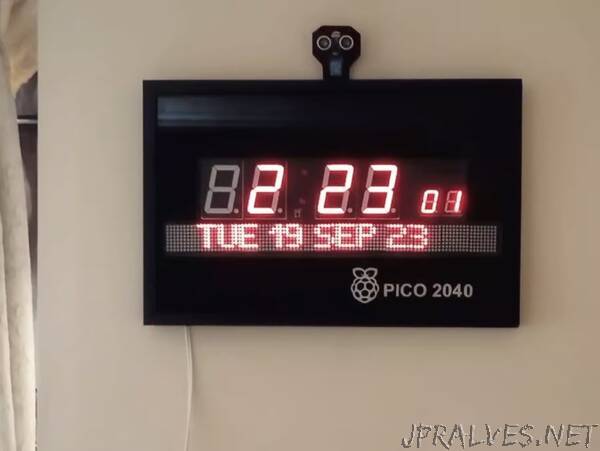
Regarding the construction I have used 2 home made PCBs, drawn with DIPTRACE and etched at home itself. Though it can be made on general purpose PCBs, it may not be get compact and neat. Two photo frames purchased from a photo framing shop were used here. The two frames were screwed together for getting enough height for placing the hardware. All the PCBs and hard wares are fixed with screws on the back plate which is finally screwed with the frame. The glass of the photo frame is painted with black enamel paint leaving space for the displays. Raspberry logo and words PICO 2040 were also printed on the front glass with white paint, which gives the clock a professional look. As such the clock looks great and no one will detect it as a DIY one!
All the functions of the clock can be controlled fully with the IR remote, When Time set key is once pressed the Second digits of the clock indicate as “St”, also a message “ SET Time” displayed on second clock’s display. You can type the time required using the numeric keys on the remote and press enter key to set.Also you can leave with out any change from the set mode by pressing the home button.
Similar is the procedure for setting alarm time and date using the remote.
The Key named CH SET is used to set different modes of audio. On pressing the key the 7 segment display will change to different modes like
1. CH –on means only hour chime and half hour speak always
2 CH — nt means night mode hour chime and half hour will not work on night hours
3 —UL on means Chime is off and US sensor active always
4 CH UL nt means Chime and US sensor are under night mode and will not work during the pre-fixed night hours Etc.. etc
On pressing the enter key the mode is set and the first clock send the data to the second clock for usage and writing on its SD card for future use. Here also we can return with out setting any thing by pressing the home key.
On pressing the key labelled Temp, the first clock request and collect the current temperature from the second clock and display on its Seven segment display
AL POF key is used to set the Alarm permanently in off mode or in active mode. Pressing the button will toggle the mode from On and Off, and can be set by pressing enter key. If not in off mode the clock will blow alarm on all the days when reaching the set time.
PL OFF key is for stopping the alarm once it blown, and also to stop any music playing on the MP3 player
The VOL Button is meant for setting the volume of MP3 player. Maximum volume level is 30 which is divided in to 10 steps. Press the button multiple times to the required level and press the enter key to set the volume
An On-Off button is provided in the remote to On and blank both the LED displays.While in off mode only the displays gets blank, but the clock works normally with all it set modes”