
“This instructable is about building standalone computers running a BASIC dialect suitable for IoT and interactive work. It uses low cost components that are readily available and can be integrated without much difficulty.
So why running BASIC on a microcontroller? Everyone who has programmed on 80s microcontrollers misses one thing on modern computer. It is the ease of use when you want to do something quickly. You could just type in a small program interactively, debug it and step by step extend it. No compiler, IDE, and other stuff in your way. Many IoT programs are really simple. Read a sensor and transfer the data. This can very well done with a really simple programming language.
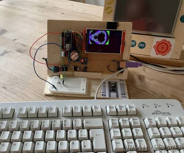
The computer which is the main character in this story is based on an Arduino RP2040 connect. It has an SD card filesystem, and a 480x320 colour display with 30x20 text character and a 16x16 default font. It has a real time clock for exact time and a PS2 keyboard for input. A thermo printer can be connected serially. Any 7-12V power supply can be used as the board has a 5V voltage regulator. There is 64kB of usable BASIC memory and 2 GB disk space.
The BASIC interpreter is a full featured language with strings, graphics, floating point support, Arduino I/O, and a few other useful features.
The computer can be build on a large breadboard almost without any soldering (except for the PS2 plug). Preferably a 10x15 cm circuit board is used for a real stable hardware setup.
Core components of the computer are
- Arduino RP2040 connect microcontroller board (https://store.arduino.cc/products/arduino-nano-rp2040-connect)
- ILI9488 based display shield. These shields are SPI based, have an SD card slot, and an optionally touch input which will not be needed here. The shields are very common. Please make sure to buy the SPI based ones for this hardware project.
- A voltage level converter.
- An old PS2 keyboard and a PS2 plug.
- Either a large breadboard or preferably a 10x15 cm circuit board.
- Breadboard cables if you build on a breadboard.
- Optionally an SD card.
- Optionally a DS1307 or DS3231 real time clock.
- Optionally a 7805 voltage regulator, the 0.1 uF and 0.33 uF capacitors, plus a power plug.
- Optionally a serial thermo printer.
- Some plywood and a small breadboard for the stand, plus a power supply.”