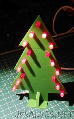
Being in the Christmas season we will be building a circuit that fits the Christmas spirit - a Christmas tree with LEDs.
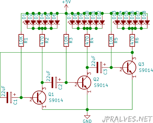
This circuit is very simple and allows you to make the LEDs blink alternately in three groups. The circuit is an oscillator.
The frequency of oscillation is dependent on the values of the resistors (R2, R4 and R6) that charge the capacitors (C1, C2 and C3) and the value of these.
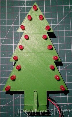
In our case, the circuit was made with red LEDs, but LEDs of other colors can be used as long as they are all in the same group and the respective resistance (R2, R4 or R6) is changed.
What is an LED? An LED is a special type of diode that emits light when current passes through it. As a diode, it only allows current to flow in one direction. An LED has two pins called the anode and cathode.
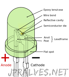
Typically the cathode pin (-) is shorter than the anode pin (+). Another way to check which is the anode and cathode is by looking at the smooth surface on the cathode side.
LEDs today come in different shapes and colors, and different electrical characteristics.
Summary of features of the 5mm single-color LEDs:
| Color | Voltage Drop | Current Consumption |
|---|---|---|
| Red | < 2V | 20mA |
| Orange | < 2.1V | 20mA |
| Yellow | < 2.2V | 20mA |
| Green | < 2.2V | 20mA |
| Blue | < 3.7V | 30mA |
| White | 3.5V | 20mA |
Note: There are other types of LEDs - RGB, Bi-Color, Tri-color, Flashing-LEDs, etc., but they have not been mentioned to simplify the explanation.
To get the value of the resistance to be used we must use Ohm’s law: R = V / I
From the circuit we know that the input voltage is 5V. As the value of I in is Amperes we consider 0.02 A. (20mA)
The Voltage to be dissipated is 5 - 2 = 3V, which makes the minimum resistance value to be 3/0.02 = 150 Ohm.
This is for the maximum intensity of the LEDs. As the LEDs can be seen with less intensity we will use a higher value (470 Ohm).
To see the circuit at work you can see it online at falstad.
You can see the 3D model that was made for this circuit (with the shape of the Christmas tree) here.
Schematic
Bill of materials (BOM)
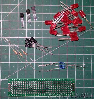
- 17x 5mm Red LEDs (D1 to D17)
- 3x Resistor 470 Ohms (R2, R4, R6)
- 3x Resistor 10K Ohms (R1, R3, R5)
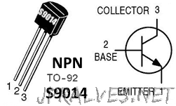
- 3x NPN Transistor S9014 (Q1, Q2, Q3)
- 3x 22uF 16V Electrolytic Capacitors (C1, C2, C3)
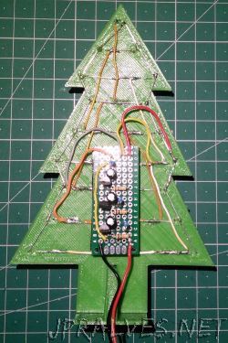
- 1x Protoboard with 15x6 holes
IC/Components Pin-out