Today we will build a circuit that detects the interruption of an infrared beam allowing an alarm to be created.
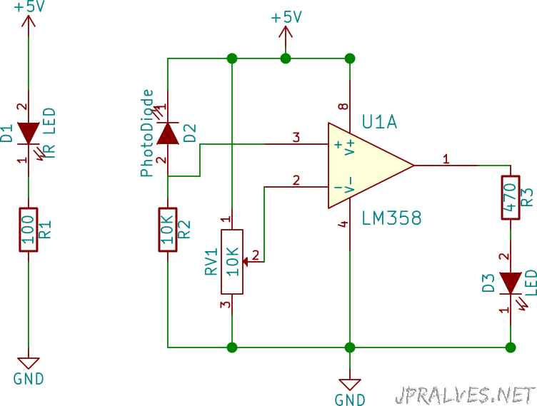
The LM358 IC has two comparators. Pin 3 which is the non-inverted end of the voltage comparator is connected to the photodiode and the inverted pin (pin 2) is connected to a 10K variable resistor. The output of the comparator is connected to a resistor and in turn to an LED.
When the infrared beam is reflected in the obstacle and picked up by the photodiode, the voltage at the non-inverted end of the voltage comparator is greater than at the inverted end and the output of the comparator will be high. As the comparator output is connected to the LED, when the LED is high it means there are no obstacles.
The detection range can be adjusted by the variable resistance.
This circuit was based on the circuit shown in page.
Schematic
Bill of materials (BOM)
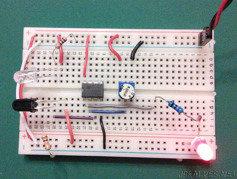
Circuit:
- 1x 100 Ohms Resistor (R1)
- 1x 10K Ohms Resistor (R2)
- 1x 470 Ohms Resistor (R3)
- 1x 10K Ohms Variable Resistor (RV1)
- 1x IC LM358 (U1)
- 1x IR LED (D1)
- 1x Photodiode (D2)
- 1x 5mm Red LED (D3)
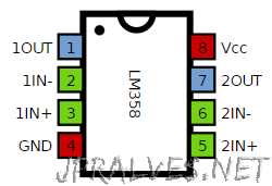
IC/Components Pin-out