Today we will build a circuit that detects the interruption of an infrared beam allowing an alarm to be created.
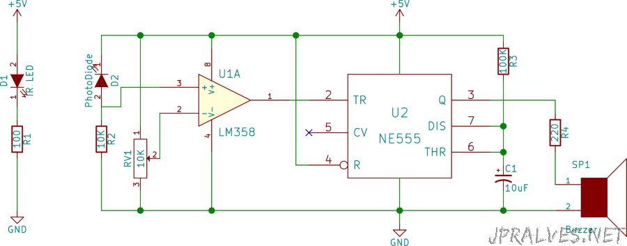
The LM358 IC has two comparators. Pin 3 which is the non-inverted end of the voltage comparator is connected to the photodiode and the inverted pin (pin 2) is connected to a 10K variable resistor. The comparator output is connected to the NE555 IC trigger pin. The NE555 is set to mono-stable mode.
While the infrared beam is being viewed by the photodiode, the voltage at the non-inverted end of the voltage comparator is greater than at the inverted end and the output of the comparator will be high. As the comparator output is connected to the 555 trigger pin, when it is high the 555 output is low.
If there is an interruption of the infrared beam the voltage in the comparator inverts and becomes, for some moments, higher than in the non inverted end. This causes the comparator output to go low and as such the “Trigger” of the 555 is low, starting its timer. As soon as this timer starts the buzzer will sound. The duration of the signal can be modified by changing the values of the resistor R3 or the capacitor C1.
Typically the range of an infrared LED is 2 meters (can be increased by means of a lens). A “Relay” can be used to do trigger for other types of alarms. Both the infrared LED and the photodiode must be perfectly aligned so that the infrared beam strikes directly at the photodiode. The sensitivity of the sensor can be changed by adjusting the variable resistor.
This circuit was based on the circuit shown in this page.
Schematic
Bill of materials (BOM)
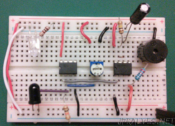
Circuit:
- 1x 100 Ohms Resistor (R1)
- 1x 10K Ohms Resistor (R2)
- 1x 100K Ohms Resistor (R3)
- 1x 220 Ohms Resistor (R4)
- 1x 10K Ohms Varible Resistor (RV1)
- 1x IC LM358 (U1)
- 1x IC NE555 (U2)
- 1x 10uF Electrolytic Capacitor (C1)
- 1x IR LED (D1)
- 1x Photodiode (D2)
- 1x Buzzer (SP1)
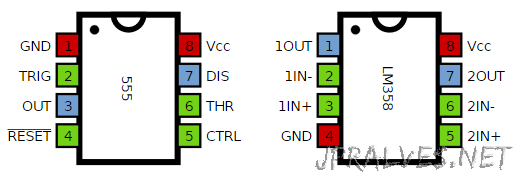
IC/Components Pin-out