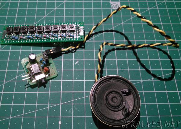
Today we will build a circuit that uses the IC 555 along with buttons and resistances to play the 9 musical notes.
This circuit has a wave generator 555 configured as an astable multivibrator circuit. This type of operation is characterized by a square wave width output defined by the designer. The frequency of the output wave can be controlled by the resistance between pins 7-8 and 2-7 in addition to the capacitor connected to pin 2 and GND. The resulting frequency can be calculated according to the following equation:
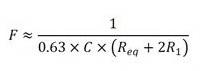
Where the Req is the result according to the button being pressed.
This way we can make sound similar to a basic digital piano that regulates the output frequency for musical notes.
Notes are played on the following frequencies:
| Note | Frequency | Resistors |
|---|---|---|
| RE1 | 493Hz | R2-R3 |
| DO | 440Hz | R2-R4 |
| SI | 392Hz | R2-R5 |
| LÁ | 349Hz | R2-R6 |
| SOL | 329Hz | R2-R7 |
| FÁ | 293Hz | R2-R8 |
| MI | 261Hz | R2-R9 |
| RE | 246Hz | R2-R10 |
| DO | 200Hz | R2-R11 |
This circuit has been adapted from a circuit that is in the following link.
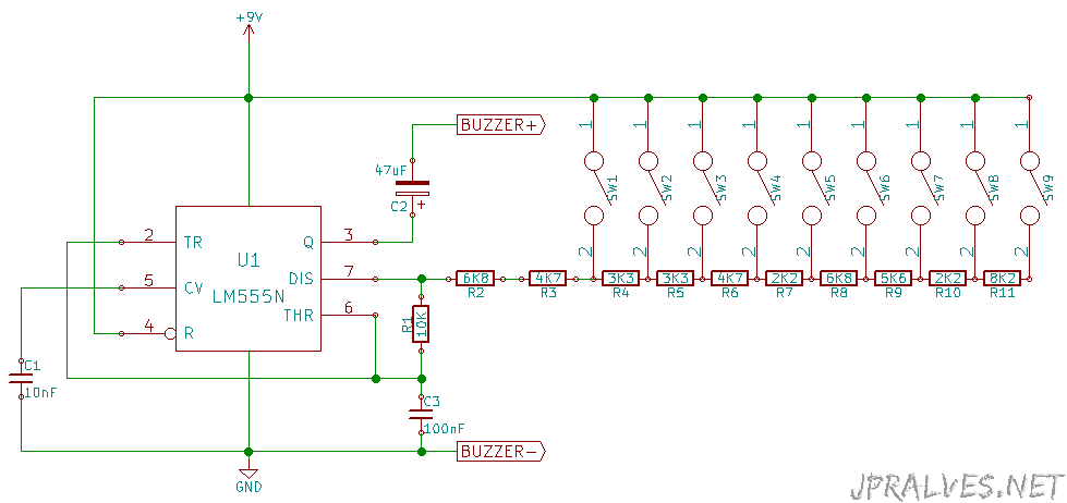
Schematic
Bill of materials (BOM)
Circuit:
- 1x IC NE555P (U1)
- 1x 10K Ohms Resistor (R1)
- 2x 6K8 Ohms Resistor (R2,R8)
- 2x 4K7 Ohms Resistor (R3,R6)
- 2x 3K3 Ohms Resistor (R4,R5)
- 2x 2K2 Ohms Resistor (R7,R10)
- 1x 5K6 Ohms Resistor (R9)
- 1x 8K2 Ohms Resistor (R11)
- 9x SPST Button (SW1-9)
- 1x 10nF Ceramic Capacitor (C1)
- 1x 47uF Electrolytic Capacitor (C2)
- 1x 100nF Ceramic Capacitor (C3)
- 1x Speaker 8 Ohm from 0.25W to 1W
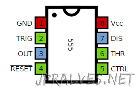
IC/Components Pin-out