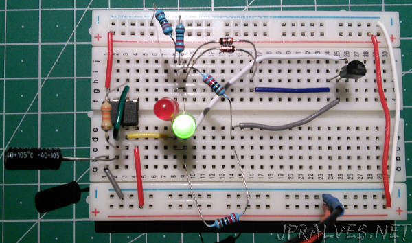
Today will be presented a circuit to test bipolar PNP and NPN transistors . It is a circuit based on the 555. This circuit lets you check the type of transistor we have and if it is working properly or not.
As the circuit is mounted, the 555 is running at 2 Hz. Pin 3 oscillates between 0 and a positive voltage value. At the other end of the circuit a voltage divider is made that is approximately 4.5V in the middle. This allows the LEDs to light up alternately when there is no connected transistor.
If a functioning transistor is turned on, it will short-circuit the pair of LEDs when the voltage goes in one direction and only one of the LEDs will blink. If PNP will blink red, if NPN will blink green.
If the transistor is open, both LEDs will blink and if the transistor is closed none of the LEDs will blink.
Schematic
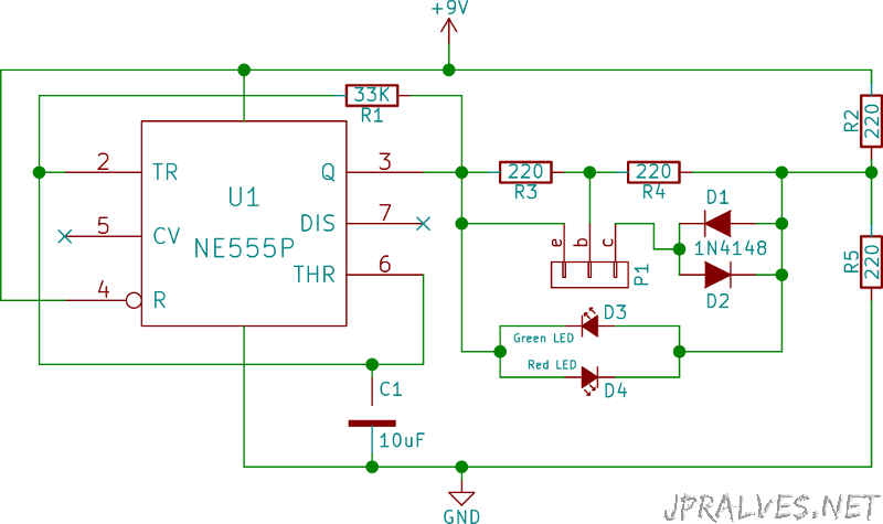
The pins c, b, and refer to the c - Collector, b - Base, and - Emitter of the transistor.
Notice:
The circuit was based on the circuit presented in this page
Bill of Materials (BOM)
- 1x NE555P (U1)
- 4x 220 Ohms Resistors (R2-R5)
- 1x 33K Ohm Resistor (R1)
- 1x 10uF Electrolytic Capacitor (C1)
- 2x 1N4148 Diode (D1-D2))
- 1x red LED (D3)
- 1x green LED (D4)
- 1x Bateria de 9V
For testing:
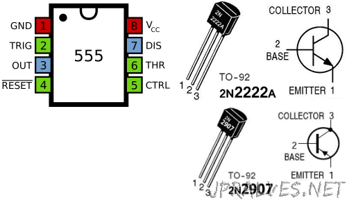
- Bipolar PNP and NPN bipolar transistors (Ex: 2N2222, 2N2907, etc …)
IC Pin-out