Increasingly, when designing a circuit, we find components that operate at different voltages than the microcontroller.
This requires that, to work with them, it is necessary to implement a level shifter, that is, to ensure that there is a transition between different component voltages.
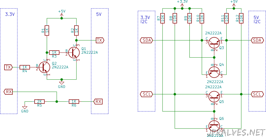
Two circuits were implemented, one for RX / TX communication and the other one for the I2C/TWI bus. In the first, it is a unidirectional level-shifter and in the second a bidirectional level-shift.
In the first circuit the most complex part to do is to ensure that the low voltage goes up enough to ensure that what is considered to be 1 in the 3.3V logic is also considered to be 1 in the 5V logic (3.3V to 5V TX). In the opposite direction the solution is simpler and a voltage divider with resistances can be used (RX from 5V to 3.3V).
In the second circuit (based on Jim Hagerman’s work) each of the Clock (SCL) and Data (SCA) lines are converted through use Of two NPN transistors and two resistors. The circuit adds additional resistance to control whether or not the signal is active (ENABLE).
There are already modules specifically prepared to do this work, however the circuits presented are simple enough to be implemented with few components and quickly.
Schematic
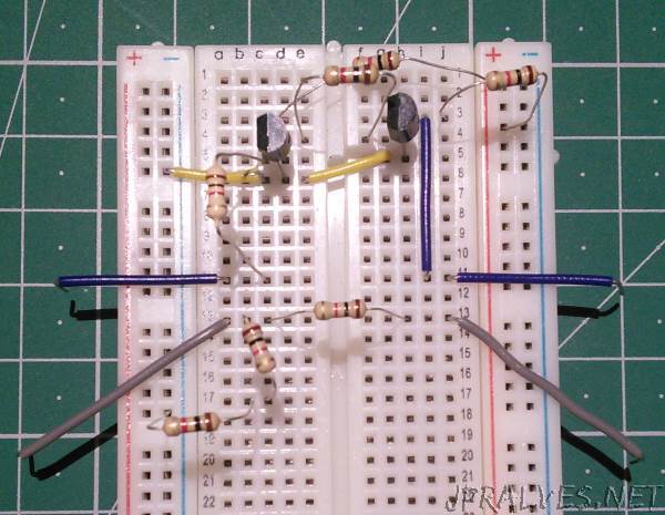
Bill of materials (BOM)
Circuit 1:
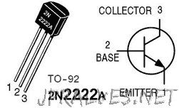
- 2x 2N2222 NPN Transístor (Q1 and Q2)
- 5x 1K Ohms Resistors (R1 to R4 and R6)
- 1x 2K Ohms Resistor (R5)
Circuit 2:
- 6x 10k Ohms Resistors (R7 to R12)
- 4x 2N2222 NPN Transistor (Q3 to Q6)
IC Pin-out