In this article we will build a circuit to control the position of a servo. Servos are typically small in size and are typically used to operate remotely controlled robots, cars or airplanes via radio. They are also used in industrial applications, robotics, manufacturing, etc.
A servo is built inside the motor unit and has a positionable shaft, which is usually equipped with a gear. The motor is controlled by an electrical signal (PWM), which determines the amount of movement of the shaft.
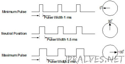
Servos are controlled by sending a variable width electrical pulse, or pulse width modulation (PWM), through the control wire. There is a minimum pulse, a maximum pulse, and a repetition rate. A servo motor can normally only rotate 90° in either direction for a total of 180° of motion. The neutral position of the motor is defined as the position where the servo has the same amount of rotation at potential either clockwise or counterclockwise. The PWM sent to the motor determines the position of the shaft, and based on the duration of the pulse sent through the control wire the rotor will rotate to the desired position. The servo motor waits to see a pulse every 20 milliseconds (ms), and the length of the pulse determines how much the motor turns. For example, a pulse of 1.5ms in turn will bring the motor to the 90° position. Shorter than 1.5ms moves it to 0° C and longer than 1.5ms will turn the servo 180°, as diagrammed below.
When the servos are given the order to move, they will move into position and hold that position. If an external force is made against the servo while the servo is holding a position, the servo will resist from changing position. The maximum amount of force the servo can exert is called the servo torque rating. Servos will not hold their position forever though; the position thrust must be repeated to instruct the servo to stay in position.
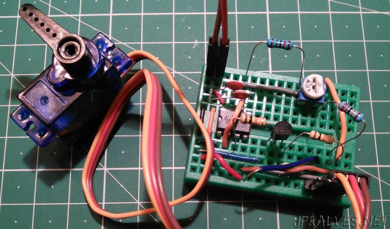
This circuit built using a 555 IC, allows changing the position of the 100K trimmer to change the position of the servo.
Schematic
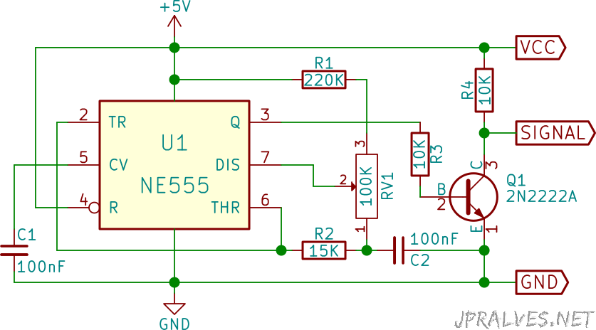
Bill of materials (BOM)
- 1x IC NE555
- 1x 220K Ohms Resistor (R1)
- 1x 15K Ohms resistor (R2)
- 2x 10K Ohms resistor (R3, R4)
- 1x 100K Ohms Variable resistor (RV1)
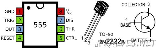
- 1x NPN Transistor 2N2222A (Q1)
- 2x 100nF Ceramic Capacitors (C1, C2)
- 1x Servo (HXT900)
IC/Components Pin-out