
Today we will build a circuit to control DC motors.
Electric motors of all kinds work thanks to electromagnetism. They convert electric energy into mechanical energy. DC motors are relatively simple control motors.
They are motors that have two modes of operation and that allows them to rotate in both directions depending on the way the polarity of the DC circuit is applied.
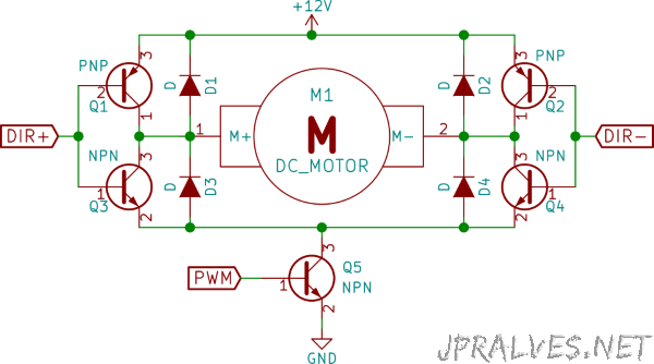
Usually when you want to control this type of motors, the so-called H bridges are used that can be constructed with 4 bipolar transistors (two NPN and two PNP) paired so that, depending on the voltages applied at two points, we can control the direction of motor movement. They have the designation of bridge H because the design of the circuit takes the form of the letter H.
Since any motor is also a generator it is needed to prevent the so-called inductive currents that are generated when the motor turns into a generator. This step is solvable by placing diodes that will protect the circuit from these currents.
It should be noted that although there are two power circuits (one for control and one for powering the motors), both must share the same GND.
The use of an H-bridge for motor control enables the power supply circuit of the motor, which typically needs a voltage and more current, to be separated from the control circuit.
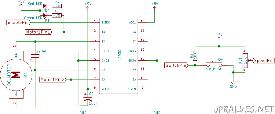
In the circuit that we will build we will use an IC designated by L293D. This already incorporates almost everything we need and greatly simplifies the circuit. The motor speed is controlled by PWM applied to the IC ENABLE pin.
This IC is very interesting because it has four half H-bridges and allows to control motors up to 600mA.
When using different motors you should take into account the characteristics of them and the limitations of the IC in terms of maximum current that can be made available.
In order to smooth the load of the motors in the motors it is advisable to put some capacitors, this helps to avoid peaks and stabilizes the current. In the power supply, a 10 uF electrolytic capacitor with a minimum voltage higher than that used in the supply circuit should be used and a 220nF ceramic capacitor can also be used even with each motor.
Tip:
- There is a simple way to double the current that the L293D can handle. Just put another one on top of the first one.
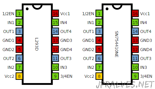
- It can also be used an alternate IC which is SN754410NE which supports up to 1A. It is necessary in this last one to add the protection diodes.
Regarding L293D, as a function of the values in pins 1,2 and 7 we have the following results:
| Pin 1 | Pin 2 | Pin 7 | Result |
|---|---|---|---|
| High | Low | High | Turn clockwise |
| High | High | Low | Turn anti-clockwise |
| High | Low | Low | Stop |
| High | High | High | Stop |
| Low | N/A | N/A | Stop |
Schematic
This is a base circuit of an H bridge built with transistors:
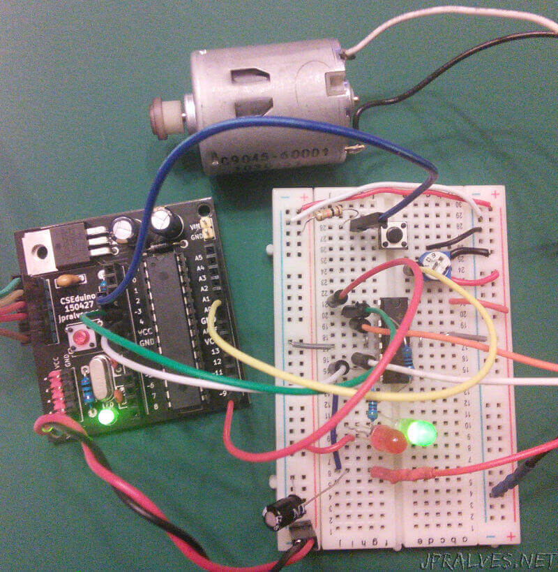
The circuit used was as follows:
Bill of materials (BOM)
Circuit:
- 1x IC L293D
- 1x SPST Button (SW1)
- 1x 10K Ohms Resistor (R2)
- 1x 470 Ohms Resistor (R1,R3)
- 1x 5mm Green LED (D1)
- 1x 5mm Red LED (D2)
- 1x 10K Ohms Variable Resistor (RV1)
- 1x 220nF Ceramic Capacitor (C1)
- 1x 10uF 25V Electrolytic Capacitor (C2)
- 1x DC Motor (M1)
IC/Components Pin-out
Code
This sketch should be loaded into an Arduino through your IDE. When the button is pressed the motor will change direction.
The potentiometer can be used to change the speed of rotation of the motor.
const int switchPin = 2;   // botão
const int speedPin = A0;   // ligado no pino do meio do Potenciometro
const int motor1Pin1 = 3;  // pino 2 do L293D
const int motor1Pin2 = 4;  // pino 7 do L293D
const int enablePin = 9;   // pino 1 do L293D (PWM)

void setup() {
  pinMode(switchPin, INPUT);

  pinMode(motor1Pin1, OUTPUT);
  pinMode(motor1Pin2, OUTPUT);
  pinMode(enablePin, OUTPUT);

  digitalWrite(enablePin, HIGH);
}

int direction = false;

void loop() {
  int speed = analogRead(speedPin);
  speed = map(speed, 0, 1023, 0, 255);
  analogWrite(enablePin, speed); // PWM
  if (digitalRead(switchPin) == LOW) {
    direction = !direction;
  }

  if (direction) {
    digitalWrite(motor1Pin1, LOW);
    digitalWrite(motor1Pin2, HIGH);
  } else {
    digitalWrite(motor1Pin1, HIGH);
    digitalWrite(motor1Pin2, LOW);
  }
}
// Sketch uses 1,772 bytes (5%) of program storage space. Maximum is 32,256 bytes.
// Global variables use 17 bytes (0%) of dynamic memory, leaving 2,031 bytes for local variables. Maximum is 2,048 bytes.