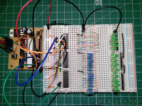
The circuit presented today is a circuit built with 3 Shift Registers - 74HC595.
This circuit allows controlling up to 24 outputs - in the case of LEDs and controlling them independently.
A CSEduino was used to control the 24 outputs. Since only 4 pins of the ATMega328P were used this micro-controller could have been replaced with a smaller / simpler one.
It could be used a micro-controller of the ATTiny family that is similar to the ATMega but which is cheaper / smaller and have fewer features.
The 74HC595 is a very common IC that allows you to expand the number of outputs since it implements a Series to Parallel interface. It allows with only 3 pins of the micro-controller to control up to eight output pins. Additionally it allows to be connected in cascade and thus allowing the control of still more outputs using the same 3 pins of the microcontroller.
The operation mode of the 74HC595 is as follows:
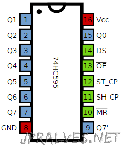
- Lower the LATCH pin (also called ST_CP or RCLK)
- The bits are sent one by one as follows:
- Lower the CLOCK pin (also called SH_CP or SRCLK)
- Sends the bit to the DATA pin (also called DS or SER)
- Raises the CLOCK pin (also called SH_CP or SRCLK)
- Note: You must send as many eight-bit (byte) groups as the 74hc595 are connected
- Raise the LATCH pin (also called ST_CP or RCLK)
In addition, the 74HC595 OE pin (also designated G) can be used to control the brightness of the LEDs by attaching the pin to a pin with PWM.
The Cascade is made by also connecting the CLOCK and LATCH pins on the other integrated ones and connecting the pin Q7’ of the first chip to the DATA pin of the second one and the Q7’ of the second chip to the DATA pin of the third chip.
Schematic
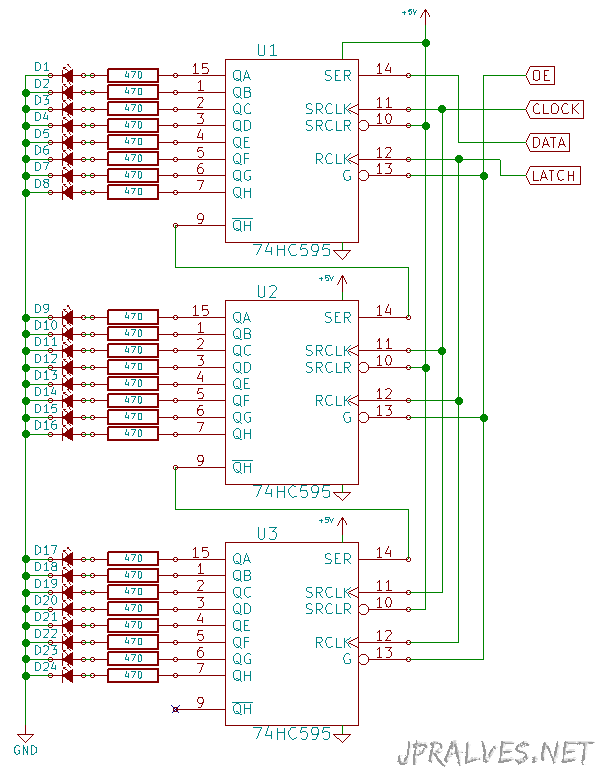
Note: The schematic only shows the connections between the 74HC595 and the LEDs.
The circuit for CSEduino can be consulted on the [CSEduino page] ({filename}/pages/CSEDuino/cseduinoworld.md). An Arduino can also be used.
Bill of materials (BOM)
- 3x 74HC595 - 8-bit serial-in, serial or parallel-out shift register with output latches; 3-state (U1, U2 e U3)
- 24x 3mm or 5mm LED (D1-D20)
- 24x 470 Ohms Resistors (R1-R20)
IC Pin-out
To program the Micro-controller, the Arduino IDE was used.
Code
The Sketch used:
/*

  Created by Joao Alves on 2015-Jun-8.
  Copyright 2014 - Under creative commons license 4.0:
          Attribution-ShareAlike CC BY-SA
  This software is provided "as is", without technical support, and with no
  warranty, express or implied, as to its usefulness for any purpose.

  Description:
  Circuit with defined 24-Led sequences.

  The circuit:
  * 3 x 74HC595
      - 1st 74HC595 - Pin DATA  - D10
      - 2nd 74HC595 - Pin DATA - 1st 74HC595 Pin Q7'
      - 3rd 74HC595 - Pin DATA - 2st 74HC595 Pin Q7'
      - All 74HC595 - Pin LATCH - D12
      - All 74HC595 - Pin CLOCK - D11
      - All 74HC595 - Pin OE - D9

  Created on 2015-Jun-8
  By Joao Alves <jpralves@gmail.com>

*/
#include <avr/pgmspace.h>

#if defined (__AVR_ATtiny45__)
#define LATCH 1
#define CLOCK 2
#define DATA 3
#define INTENSITY 0
#else
#if defined(__AVR_ATmega328P__) || defined(__AVR_ATmega168__)
    //Code here
#define LATCH 12
#define CLOCK 11
#define DATA 10
#define INTENSITY 9
#endif
#endif

const int patternDelay = 200;

const byte test_pattern[][3] PROGMEM = {
{0,0,0},

{0,0,1},
{0,0,2},
{0,0,4},
{0,0,8},
{0,0,16},
{0,0,32},
{0,0,64},
{0,0,128},

{0,1,0},
{0,2,0},
{0,4,0},
{0,8,0},
{0,16,0},
{0,32,0},
{0,64,0},
{0,128,0},

{1,0,0},
{2,0,0},
{4,0,0},
{8,0,0},
{16,0,0},
{32,0,0},
{64,0,0},
{128,0,0}
};

void testLeds() {
    for (int numberToDisplay = 0; numberToDisplay < sizeof(test_pattern)/3; numberToDisplay++) {
    digitalWrite(LATCH, LOW);
    // shift out the bits:
    shiftOut(DATA, CLOCK, MSBFIRST, pgm_read_byte(&(test_pattern[numberToDisplay][0])));
    shiftOut(DATA, CLOCK, MSBFIRST, pgm_read_byte(&(test_pattern[numberToDisplay][1])));
    shiftOut(DATA, CLOCK, MSBFIRST, pgm_read_byte(&(test_pattern[numberToDisplay][2])));
    //take the latch pin high so the LEDs will light up:
    digitalWrite(LATCH, HIGH);
    delay(100);
    }
}

void setup() {
  //set pins to output so you can control the shift register
  pinMode(LATCH, OUTPUT);
  pinMode(CLOCK, OUTPUT);
  pinMode(DATA, OUTPUT);
  pinMode(INTENSITY, OUTPUT);
  digitalWrite(INTENSITY, LOW);  // Funciona ao contrário
  testLeds();
}

const byte pattern[][3] PROGMEM = {
{1,0,0},
{1,1,0},
{1,1,1},
{2,1,1},
{2,2,1},
{2,2,2},
{4,2,2},
{4,4,2},
{4,4,4},
{8,4,4},
{8,8,4},
{8,8,8},
{16,8,8},
{16,16,8},
{16,16,16},
{32,16,16},
{32,32,16},
{32,32,32},
{64,32,32},
{64,64,32},
{64,64,64},
{128,64,64},
{128,128,64},
{128,128,128},
{0,0,0},
{1,0,0},
{1,1,0},
{1,1,1},
{3,1,1},
{3,3,1},
{3,3,3},
{7,3,3},
{7,7,3},
{7,7,7},
{15,7,7},
{15,15,7},
{15,15,15},
{31,15,15},
{31,31,15},
{31,31,31},
{63,31,31},
{63,63,31},
{63,63,63},
{127,63,63},
{127,127,63},
{127,127,127},
{255,127,127},
{255,255,127},
{255,255,255},
{0,0,0},

{128,0,1},
{64,0,2},
{32,0,4},
{16,0,8},
{8,0,16},
{4,0,32},
{2,0,64},
{1,0,128},
{0,1+128,0},
{0,2+64,0},
{0,4+32,0},
{0,8+16,0},
{0,4+32,0},
{0,2+64,0},
{0,1+128,0},
{1,0,128},
{2,0,64},
{4,0,32},
{8,0,16},
{16,0,8},
{32,0,4},
{64,0,2},
{128,0,1}
};

void loop()
{
    for (int numberToDisplay = 0; numberToDisplay < sizeof(pattern)/3; numberToDisplay++) {
      digitalWrite(LATCH, LOW);
      // shift out the bits:
      shiftOut(DATA, CLOCK, MSBFIRST, pgm_read_byte(&(pattern[numberToDisplay][0])));
      shiftOut(DATA, CLOCK, MSBFIRST, pgm_read_byte(&(pattern[numberToDisplay][1])));
      shiftOut(DATA, CLOCK, MSBFIRST, pgm_read_byte(&(pattern[numberToDisplay][2])));
      //take the latch pin high so the LEDs will light up:
      digitalWrite(LATCH, HIGH);
      delay(patternDelay);
    }
}

// Sketch uses 1,646 bytes (5%) of program storage space. Maximum is 32,256 bytes.
// Global variables use 9 bytes (0%) of dynamic memory, leaving 2,039 bytes for local variables. Maximum is 2,048 bytes.
This sketch is ready to work with the Atmega328P as well as simpler micro-controllers.
The Sketch above presents a simple way to save data in flash. This method involves some aspects:
- the header file
<avr/pgmspace.h>must be included to store data in flash memory - Variables should reference in their declaration the definition PROGMEM
- This variables should be accessed with special functions named pgm_read_byte or by pgm_read_word
- The variables must be declared as const (since cannot be changed during runtime).
This circuit was used to create an animated Christmas star.