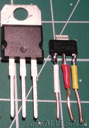
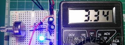
These circuits were made using two common adjustable voltage regulators - the LM317T and the AMS1117ADJ.
The LM317T is an adjustable voltage linear regulator that is very popular. It was invented in 1970 and is still used today.
This is very cheap component.
Due to its characteristics, the way it reduces the output voltage is done at the expense of heat dissipation, which makes it inefficient.
It can have output voltages between 1.25 V and 37 V.
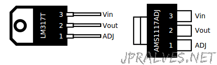
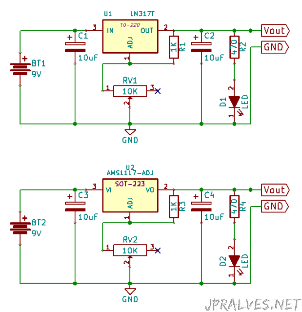
The LM317 has three pins: VIn, Vout and ADJ. In order to define the voltage in the Vout the circuit shown below is used:
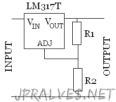
This presents in its configuration two resistors R1 and R2. The Vout = Vref * (1 + R1 / R2). The reference voltage value is usually around 1.25V.
It supports a maximum current of 1A. Some models support up to 1.5A.
The capacitors are advised and in some cases necessary to decrease / eliminate the effects of the frequencies introduced by the other elements of the circuit.
They also serve to mitigate the effects of peak consumption.
The AMS1117 in addition to being of a different format (SOT-223) maintains compatibility with the LM317T in terms of pins.
It is an integrated more advanced than the previous ones and with a superior efficiency.
| IC | Format | Input | Output | Max Amp | DataSheets |
|---|---|---|---|---|---|
| LM317T | TO-220 | 3V a 40V | 1.25V a 37V | 1A | Link |
| AMS1117-ADJ | SOT-223 | 1.5V a 12V | 1.25V a 9.7V | 1A | Link |
Schematic
Bill of materials (BOM)
All circuits need the following components in addition to the voltage regulator:
2x 10uF 50V Electrolytic Capacitors
- 1x 1k Ohm Resistor
- 1x 10K Ohm Variable Resistor
- 1x 470 Ohm Resistor for the LED
- 1x 5mm LED
- 1x 9V Battery
IC Pin-out