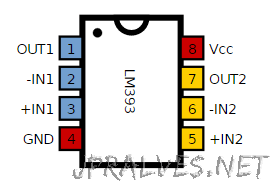
In the circuit of this article we will build a voltage comparator using an integrated chip called LM393.
The LM393 is a dual difference comparator. This means that you have two independent voltage comparators.
The circuit compares the input voltages and detects which has the highest value. Based on this information, decisions are made that may be based on what has the highest or lowest input. A comparator is very useful in circuits where it is necessary to measure levels and if the circuit is to act in a certain way based on the value of the input being greater or less than a certain interval.
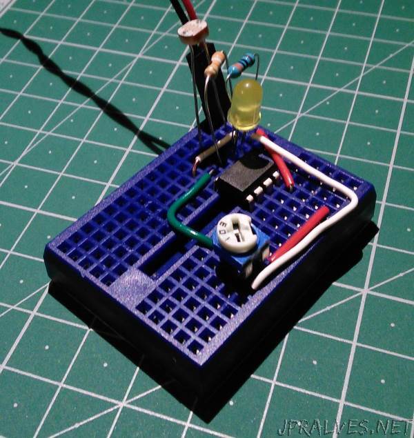
The built circuit is a basic night light system, which is a circuit that lights the LED when it is dark. A photoresistance will be used to observe the existence / absence of light. This type of resistance has different values when light strikes or when it is dark. When the surface of the photoresistance is in the dark the resistance of the same is very high. When exposed to light the resistance is low.
The voltage passing through a component is directly proportional to the resistance the component provides. In this sense, a voltage divider circuit was mounted with Photo-resistance and a fixed-value resistor. When it is placed in the dark the Photo-resistance will consume most of the voltage, since as already said there is a very high resistance in the dark. When placed in the light, the photoresistance will only consume a small part of the voltage, assuming that the fixed resistance is much larger than the photoresistance value. If a good reference voltage is given as input to the non-inverted pin of the ampop, and the photoresistance voltage is above that of the reference when exposed to the dark and below the reference voltage when exposed to light, a circuit is useful when there is light and when it is dark (the LED will light when it is dark and will be off when there is light).
And that is why this type of comparator circuits are very useful. They are readers of voltage levels and switch off outside a certain range of values.
This circuit was based on the circuit that is in the following link.
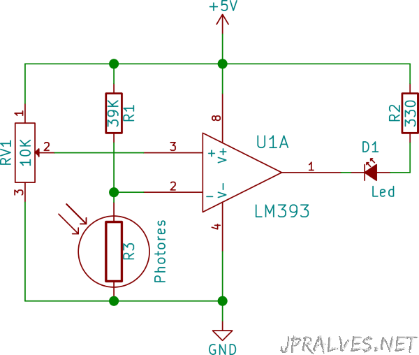
Schematic
Bill of materials (BOM)
Circuit 1:
- 1x LM393 (U1)
- 1x 39K Ohms Resistor (R1)
- 1x 330 Ohms Resistor (R2)
- 1x Photoresistor (R3)
- 1x 10K Potentiometer (RV1)
- 1x 5mm LED (D1)
IC Pin-out