
Sending information from the micro-controller to the user is extremely important to help in the interaction between the two.
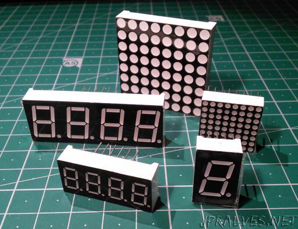
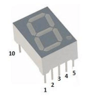
The use of 7 Segment LEDs is a common practice since they are simple to use devices that allow the sending of numerical information.
In this article we will see the control of a set of 7 Segment LEDs controlled by using a 74HC595 and a CD4511.
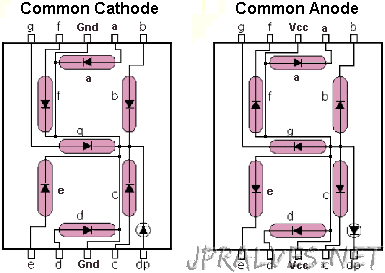
The 7 Segment LEDs have several variants and typically have 1, 2, 3 or 4 digits. They may be common cathode or common anode.
The cathode (-) indicates the negative polarity and the positive (+) anode of an energy source.
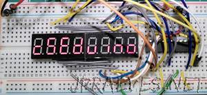
We will also see the use of another integrated - the MAX7219 - which is more powerful and allows controlling up to 8 LEDs of 7 Segments or an array of 8x8 LEDs.
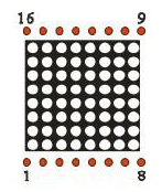
An 8x8 LED array can be Line Cathode/Anode Column or Line Anode/Cathode Column. Due to its typology, the connections must be reversed.
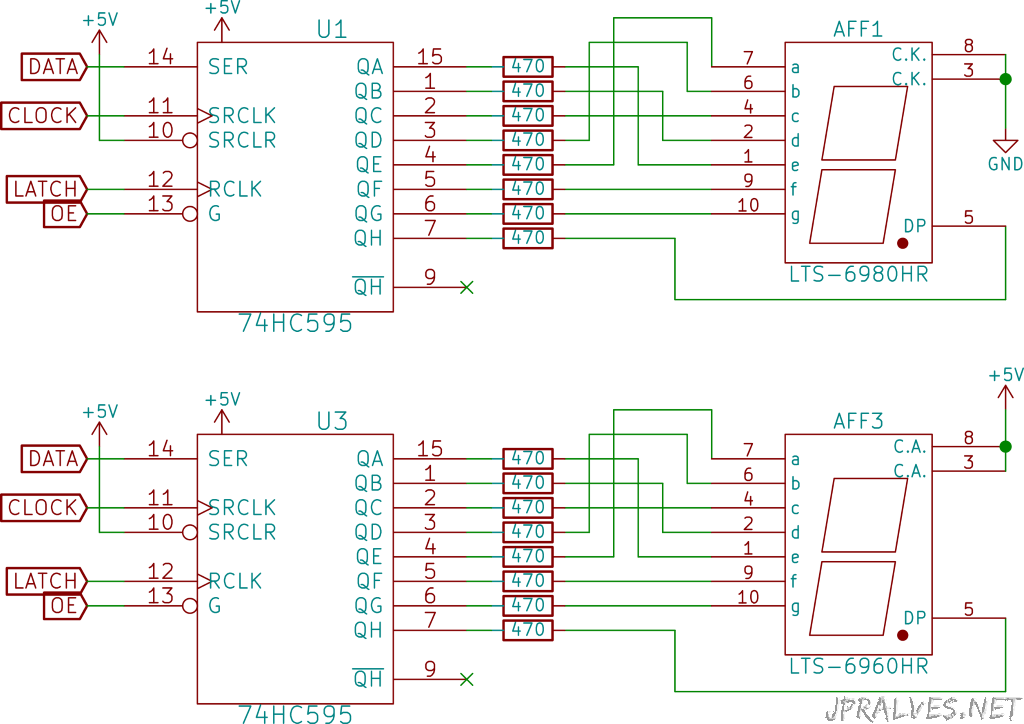
For the 74HC595 a Serial to Parallel interface is used that has already been addressed in this article.
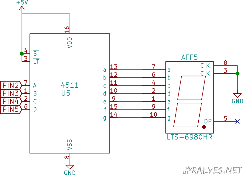
Using the CD4511 the number passed in binary in four pins is converted for the LED of 7 Segments.
In the case of MAX7219 an interface [SPI] (http://www.arduino.cc/en/Reference/SPI) is used to send the information to the integrated one.
Schematic
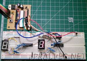
With 74HC595:
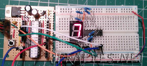
With CD4511:
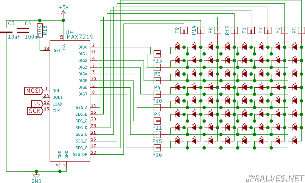
With MAX7219:
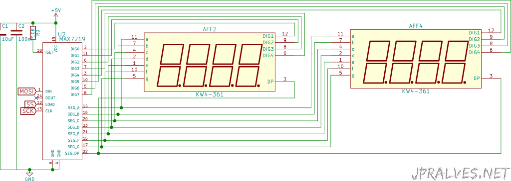
For the 8x8 LEDs Matrix:
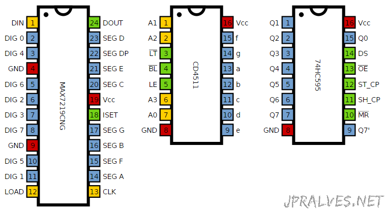
The numbering used on Segment LEDs and cube arrays is identical to DIP Chips.
The connections between the 4x 7-Segment LEDs were as follows:
| Display 4 x 7-Segments | MAX 7219 | 7-Segment Code | Segment |
|---|---|---|---|
| 1 | 21 | E | Both |
| 2 | 23 | D | Both |
| 3 | 22 | DP | Both |
| 4 | 20 | C | Both |
| 5 | 17 | G | Both |
| 6 | 7 | D4 | Left |
| 7 | 16 | B | Both |
| 8 | 6 | D3 | Left |
| 9 | 11 | D2 | Left |
| 10 | 15 | F | Both |
| 11 | 14 | A | Both |
| 12 | 2 | D1 | Left |
| 6 | 8 | D4 | Right |
| 8 | 5 | D3 | Right |
| 9 | 10 | D2 | Right |
| 12 | 3 | D1 | Right |
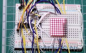
The connections between the MAX7219 and the 8x8 Matrix:
| Matriz 8x8 | MAX7219 |
|---|---|
| 9 | 22 |
| 14 | 14 |
| 8 | 16 |
| 12 | 20 |
| 1 | 23 |
| 7 | 21 |
| 2 | 15 |
| 5 | 17 |
| 13 | 2 |
| 3 | 11 |
| 4 | 6 |
| 10 | 7 |
| 6 | 3 |
| 11 | 10 |
| 15 | 5 |
| 16 | 8 |
Notice:
The circuit for CSEduino can be checked on this [page] ({filename}/pages/CSEDuino/cseduinoworld.md). An Arduino can also be used.
Bill of materials (BOM)
For the circuit with the 74HC595:
- CSEduino
- 1x 74HC595
- 8x 470 Ohm Resistors
- 1x 7-Segment LED 7 common anode
- 1x 7-Segment LED 7 common cathode
For the circuit with the CD4511:
- CSEduino
- 1x CD4511
- 8x 470 Ohm Resistors
- 1x 7-Segment LED 7 common anode
- 1x 7-Segment LED 7 common cathode
For the circuit with the MAX7219:
- CSEduino
- 1x MAX7219
- 1x 100uF Electrolytic Capacitor
- 1x 100nF Ceramic Capacitor
- 1x 10K Ohm Resistor
- 1x 8x8 LED Line cathode/column anode (788BS)
IC Pin-out
Code
The Sketch used for the 74HC595 was as follows:
//  Filename: control7Seg-74hc595.ino

#define LATCH 12
#define CLOCK 11
#define DATA 10
#define INTENSITY 9

const int patternDelay = 500;

// adder = 0 - Common Cathode
// adder = 255 - Common Anode

//const byte adder = 0;
const byte adder = 255;

const byte test_pattern[] = { 0,1,2,4,8,16,32,64,128 };

void testLeds() {
  for (int numberToDisplay = 0; numberToDisplay < sizeof(test_pattern); numberToDisplay++) {
    digitalWrite(LATCH, LOW);
    shiftOut(DATA, CLOCK, MSBFIRST, adder ? adder-test_pattern[numberToDisplay] : test_pattern[numberToDisplay] );
    digitalWrite(LATCH, HIGH);
    delay(100);
  }
}

void setup() {
  //set pins to output so you can control the shift register
  pinMode(LATCH, OUTPUT);
  pinMode(CLOCK, OUTPUT);
  pinMode(DATA, OUTPUT);
  pinMode(INTENSITY, OUTPUT);
  digitalWrite(INTENSITY, LOW);  // Funciona ao contrário
  testLeds();
}

#define _TL 64
#define _TR 16
#define _BL 1
#define _BR 4
#define _BT 2
#define _TP 32
#define _MD 128
#define _DE 8

const byte pattern[] PROGMEM = {
0,
_TP + _TR + _BR + _BT + _BL + _TL,
      _TR + _BR,
_TP + _TR +       _BT + _BL +       _MD,
_TP + _TR + _BR + _BT +             _MD,
      _TR + _BR +             _TL + _MD,
_TP +       _BR + _BT +       _TL + _MD,
_TP +       _BR + _BT + _BL + _TL + _MD,
_TP + _TR + _BR,
_TP + _TR + _BR + _BT + _BL + _TL + _MD,
_TP + _TR + _BR + _BT +       _TL + _MD
};

void loop()
{
    for (int numberToDisplay = 0; numberToDisplay < sizeof(pattern); numberToDisplay++) {
      digitalWrite(LATCH, LOW);
      shiftOut(DATA, CLOCK, MSBFIRST, adder ? adder-pattern[numberToDisplay] : pattern[numberToDisplay] );
      digitalWrite(LATCH, HIGH);
      delay(patternDelay);
    }
}
Este sketch funciona tanto para Segmento de 7 LEDs com Cátodo comum como com Ânodo comum. Para isso deverá ser alterada a variavel adder da seguinte forma:
This sketch works for both 7-LED Segments with Common Cathode and Common Anode. To do this, change the adder variable as follows:
- Common cathode: const byte adder = 0
- Common anode: const byte adder = 255
The Sketch used for the CD4511 was as follows:
//  Filename: control7Seg-cd4511.ino

// Pinos: A0, A1, A2, A3 do CD4511
const byte pins[] = { 2,3,4,5 };

void setup() {
  for (int i=0; i<sizeof(pins);i++) {
    pinMode(pins[i],OUTPUT);
  }
}

void loop() {
  for (int n=0; n<10; n++) {
    for(int i=0; i<sizeof(pins);i++) {
      digitalWrite(pins[i],n & (1 << i) ? HIGH : LOW);
    }
    delay(250);
  }
}
The Sketch used for the MAX7219 was as follows:
//  Filename: control7Seg-max7219.ino

#include "LedControl.h"

LedControl lc = LedControl(11,13,10,1);

unsigned long delaytime = 250;

void setup() {
  lc.shutdown(0,false);
  lc.setIntensity(0,8);
  lc.clearDisplay(0);
}

void writeChar(byte px, byte py, byte ch) {
   if (ch >= 32)  {
     lc.setChar(px,py,ch,false);
   } else {
     lc.setRow(px,py,ch);
   }
}

void writeArduinoOn7Segment() {
  byte cseduino[] = {'c','5','e','d',0x1c,B00010000,0x15,0x1D,'-','H','e','l','p','-','-','-'};
  for(int i = 0; i<sizeof(cseduino) - 7; i++) {
    writeChar(0, 7, cseduino[i+7]);
    writeChar(0, 6, cseduino[i+6]);
    writeChar(0, 5, cseduino[i+5]);
    writeChar(0, 4, cseduino[i+4]);
    writeChar(0, 3, cseduino[i+3]);
    writeChar(0, 2, cseduino[i+2]);
    writeChar(0, 1, cseduino[i+1]);
    writeChar(0, 0, cseduino[i]);
    delay(delaytime*1000);
  }
}

void scrollDigits() {
  for(int i=0;i<16-7;i++) {
    lc.setDigit(0, 0, i, false);
    lc.setDigit(0, 1, i+1, false);
    lc.setDigit(0, 2, i+2, false);
    lc.setDigit(0, 3, i+3, false);
    lc.setDigit(0, 4, i+4, false);
    lc.setDigit(0, 5, i+5, false);
    lc.setDigit(0, 6, i+6, false);
    lc.setDigit(0, 7, i+7, false);
    delay(delaytime);
  }
  lc.clearDisplay(0);
  delay(delaytime);
}

void loop() {
  writeArduinoOn7Segment();
  scrollDigits();
}
For this sketch to work, you need to import the Ledcontrol library from this link, into Arduino IDE.
The sketch used to control the 8x8 LEDs:
//  Filename: control8x8-max7219.ino

//We always have to include the library
#include "LedControl.h"

/*
 Now we need a LedControl to work with.
 ***** These pin numbers will probably not work with your hardware *****
 pin 12 is connected to the DataIn
 pin 11 is connected to the CLK
 pin 10 is connected to LOAD
 We have only a single MAX72XX.
 */
LedControl lc=LedControl(11, 13, 10, 1);

/* we always wait a bit between updates of the display */
unsigned long delaytime=100;

void setup() {
  /*
   The MAX72XX is in power-saving mode on startup,
   we have to do a wakeup call
   */
  lc.shutdown(0,false);
  /* Set the brightness to a medium values */
  lc.setIntensity(0,8);
  /* and clear the display */
  lc.clearDisplay(0);
}

/*
 This method will display the characters for the
 word "Arduino" one after the other on the matrix.
 (you need at least 5x7 leds to see the whole chars)
 */
void writeArduinoOnMatrix() {
  /* here is the data for the characters */
  byte a[5]={B01111110,B10001000,B10001000,B10001000,B01111110};
  byte r[5]={B00111110,B00010000,B00100000,B00100000,B00010000};
  byte d[5]={B00011100,B00100010,B00100010,B00010010,B11111110};
  byte u[5]={B00111100,B00000010,B00000010,B00000100,B00111110};
  byte i[5]={B00000000,B00100010,B10111110,B00000010,B00000000};
  byte n[5]={B00111110,B00010000,B00100000,B00100000,B00011110};
  byte o[5]={B00011100,B00100010,B00100010,B00100010,B00011100};

  /* now display them one by one with a small delay */
  lc.setRow(0,0,a[0]);
  lc.setRow(0,1,a[1]);
  lc.setRow(0,2,a[2]);
  lc.setRow(0,3,a[3]);
  lc.setRow(0,4,a[4]);
  delay(delaytime);
  lc.setRow(0,0,r[0]);
  lc.setRow(0,1,r[1]);
  lc.setRow(0,2,r[2]);
  lc.setRow(0,3,r[3]);
  lc.setRow(0,4,r[4]);
  delay(delaytime);
  lc.setRow(0,0,d[0]);
  lc.setRow(0,1,d[1]);
  lc.setRow(0,2,d[2]);
  lc.setRow(0,3,d[3]);
  lc.setRow(0,4,d[4]);
  delay(delaytime);
  lc.setRow(0,0,u[0]);
  lc.setRow(0,1,u[1]);
  lc.setRow(0,2,u[2]);
  lc.setRow(0,3,u[3]);
  lc.setRow(0,4,u[4]);
  delay(delaytime);
  lc.setRow(0,0,i[0]);
  lc.setRow(0,1,i[1]);
  lc.setRow(0,2,i[2]);
  lc.setRow(0,3,i[3]);
  lc.setRow(0,4,i[4]);
  delay(delaytime);
  lc.setRow(0,0,n[0]);
  lc.setRow(0,1,n[1]);
  lc.setRow(0,2,n[2]);
  lc.setRow(0,3,n[3]);
  lc.setRow(0,4,n[4]);
  delay(delaytime);
  lc.setRow(0,0,o[0]);
  lc.setRow(0,1,o[1]);
  lc.setRow(0,2,o[2]);
  lc.setRow(0,3,o[3]);
  lc.setRow(0,4,o[4]);
  delay(delaytime);
  lc.setRow(0,0,0);
  lc.setRow(0,1,0);
  lc.setRow(0,2,0);
  lc.setRow(0,3,0);
  lc.setRow(0,4,0);
  delay(delaytime);
}

/*
  This function lights up a some Leds in a row.
 The pattern will be repeated on every row.
 The pattern will blink along with the row-number.
 row number 4 (index==3) will blink 4 times etc.
 */
void rows() {
  for(int row=0;row<8;row++) {
    delay(delaytime);
    lc.setRow(0,row,B10100000);
    delay(delaytime);
    lc.setRow(0,row,(byte)0);
    for(int i=0;i<row;i++) {
      delay(delaytime);
      lc.setRow(0,row,B10100000);
      delay(delaytime);
      lc.setRow(0,row,(byte)0);
    }
  }
}

/*
  This function lights up a some Leds in a column.
 The pattern will be repeated on every column.
 The pattern will blink along with the column-number.
 column number 4 (index==3) will blink 4 times etc.
 */
void columns() {
  for(int col=0;col<8;col++) {
    delay(delaytime);
    lc.setColumn(0,col,B10100000);
    delay(delaytime);
    lc.setColumn(0,col,(byte)0);
    for(int i=0;i<col;i++) {
      delay(delaytime);
      lc.setColumn(0,col,B10100000);
      delay(delaytime);
      lc.setColumn(0,col,(byte)0);
    }
  }
}

/*
 This function will light up every Led on the matrix.
 The led will blink along with the row-number.
 row number 4 (index==3) will blink 4 times etc.
 */
void single() {
  for(int row=0;row<8;row++) {
    for(int col=0;col<8;col++) {
      delay(delaytime);
      lc.setLed(0,row,col,true);
      delay(delaytime);
      for(int i=0;i<col;i++) {
        lc.setLed(0,row,col,false);
        delay(delaytime);
        lc.setLed(0,row,col,true);
        delay(delaytime);
      }
    }
  }
}

void loop() {
  writeArduinoOnMatrix();
  rows();
  columns();
  single();
}
All sketchs are in a ZIP on this link