
We will present several ways to use buttons as inputs for a circuit.
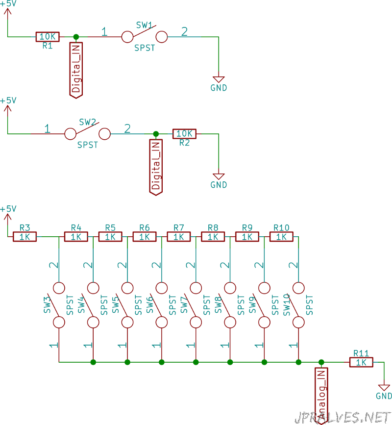
The state of a button is the most basic form of binary logic it is open or closed, however when assembling a circuit you have to keep in mind that we should always have an expected value in the circuit. For this reason it is necessary to use pull-up or pull-down resistors.
Pull-up resistors are resistors used in logic circuits that ensure that there is a known value at any time in a circuit. A logic circuit can have three logic states: high, low and floating (or high impedance). The latter state occurs when a pin is not drawn to a high or low level, and is left in a float state. A good example of this is an input pin from a microcontroller that is not connected. This causes unpredictable results and to overcome this situation, pull-up resistors are used. These resistors are identical to the others being used for this specific purpose. A typical value of pull-up resistance is 10k ohms, but may vary according to the circuit or purpose.
As opposed to the resistors of pull-up there are those of pull-down which pull instead of pulling the state of a circuit to the positive reference voltage (eg: 5V) pull to the negative voltage (ex: GND).
The correct value of resistance is limited by two factors. The power dissipation and the voltage. If the value is too low, a high current will pass through the resistor spending energy and producing heat unnecessarily. The second factor is the pin voltage when the pull-up goes into action. If the value is too high combined with a leakage current from the input pin, the input voltage may be insufficient when the circuit is open.
As a rule, the resistance value should be 10 times less than the input pin impedance value. In circuits operating at 5V voltages a pull-up value is usually between 1k and 10k ohms.
The third circuit features a way of reading multiple buttons from an analog input pin. The principle used is that of the voltage division used by the resistors. Each button is associated with a different number of resistors and then a different voltage.
Schematic
Notice:
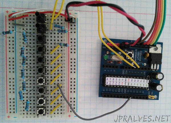
The circuits only show the part of the buttons. The connection to the microcontroller is set to sketch.
The circuit for the CSEduino can be checked in the page. An Arduino can also be used.
Bill of materials (BOM)
- 10x SPST (Switch)
- 9x 1K Ohms Resistors (R3-R11)
- 2x 10K Ohms Resistors (R1-R2)
Code
The used Sketch was as follows:
/*

  Pinos usados:
  A0 - Pino analógico
  D2 - Botão Pull-up
  D3 - Botão Pull-Down

*/

const int buttonsPin = A0;
const int puPin = 2;
const int pdPin = 3;

#define btn1      1
#define btn2      2
#define btn3      3
#define btn4      4
#define btn5      5
#define btn6      6
#define btn7      7
#define btn8      8
#define btnNONE   0

int readButtons() {               // read the buttons
  int r = btnNONE;
  int adc_key_in = analogRead(buttonsPin);
// if (adc_key_in!=0)
// Serial.println(adc_key_in);

  if (adc_key_in > 560)  r = btn8;
  if (adc_key_in > 590)  r = btn7;
  if (adc_key_in > 630)  r = btn6;
  if (adc_key_in > 675)  r = btn5;
  if (adc_key_in > 725)  r = btn4;
  if (adc_key_in > 780)  r = btn3;
  if (adc_key_in > 850)  r = btn2;
  if (adc_key_in > 925)  r = btn1;
  //...
  return r;                // when all others fail, return this.
}

void setup() {
  pinMode(puPin, INPUT);
  pinMode(pdPin, INPUT);
  pinMode(buttonsPin, INPUT);
  Serial.begin(9600);
}

void loop() {
  int button = readButtons();
  Serial.print("B1: ");
  Serial.print(digitalRead(puPin));
  Serial.print(", B2: ");
  Serial.print(digitalRead(pdPin));
  Serial.print(", BM: ");
  Serial.println(button);
}
The buttons are coded in intervals. The readButtons function returns the value of the read button or btnNONE if none is pressed.