
O envio de informação do micro-controlador para o utilizador é de extrema importância para ajudar na interação entre ambos.
A utilização de LEDs de 7 Segmentos é uma prática comum, uma vez que são dispositivos simples de usar e que permitem o envio de informação numérica.
Neste artigo iremos ver o controlo de um conjunto de LED de 7 Segmentos controlados pelo 74HC595 e pelo CD4511.
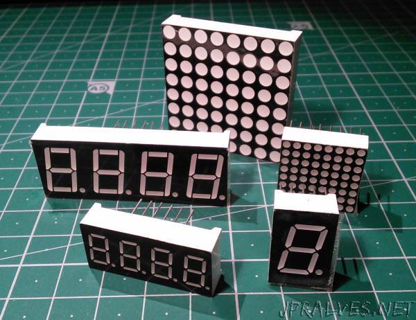
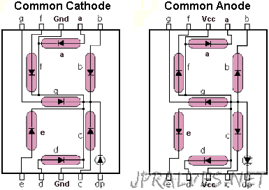
Os LED de 7 Segmentos têm diversas variantes e tipicamente têm 1, 2, 3 ou 4 dígitos. Podem ser de cátodo comum ou de anodo comum.
O cátodo (-) indica a polaridade negativa e o ânodo (+) a positiva de uma fonte de energia.
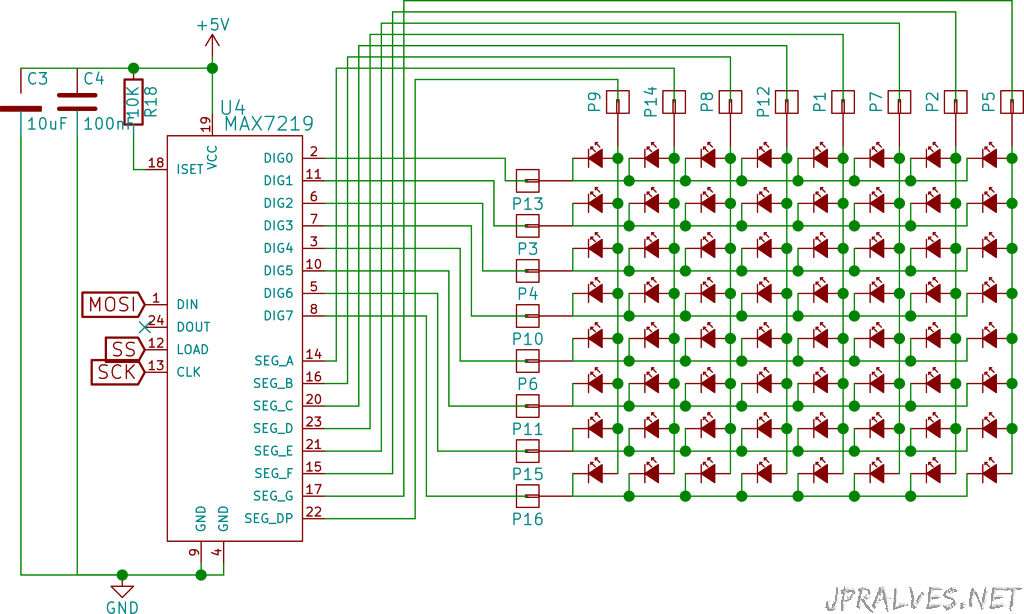
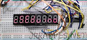
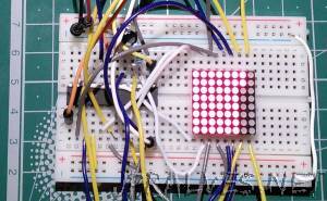
Iremos também ver a utilização de outro integrado - o MAX7219 - que é mais potente e permite controlar até 8 LEDs de 7 Segmentos
ou uma matriz de LEDs de 8x8.
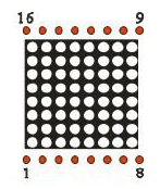
Uma matriz de LED de 8x8 pode ser Cátodo Linha/Ânodo Coluna ou Ânodo Linha/Cátodo Coluna. Em função da tipologia da mesma logo as conexões têm que ser invertidas.
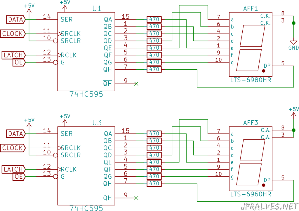
Para o 74HC595 é usada uma interface Série para Paralela que já foi abordada neste artigo.
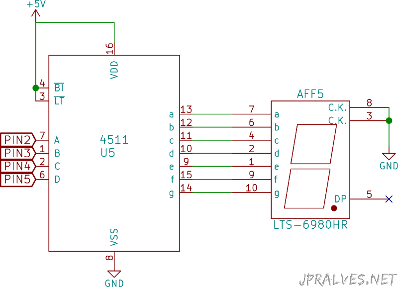
Para o CD4511 é convertido o número passado em binário em quatro pinos para o LED de 7 Segmentos.
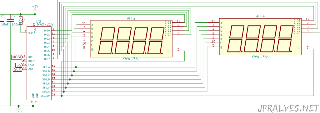
No caso do MAX7219 é usado um interface SPI para o envio da informação para o integrado.
Esquemático
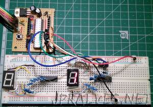
Com o 74HC595:
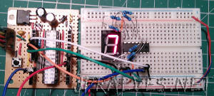
Com o CD4511:
Com o MAX7219:
Para a matriz de 8x8 LEDs:
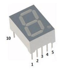
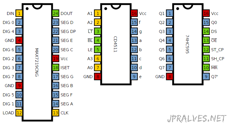
A numeração usada nos LEDs de Segmentos e nas matrizes de cubos é idêntica aos Chips DIP.
As ligações entre o LED 4x 7-Segmentos foi a seguinte:
| Display 4 x 7-Segmentos | MAX 7219 | 7-Segment Code | Segmento |
|---|---|---|---|
| 1 | 21 | E | Ambos |
| 2 | 23 | D | Ambos |
| 3 | 22 | DP | Ambos |
| 4 | 20 | C | Ambos |
| 5 | 17 | G | Ambos |
| 6 | 7 | D4 | Esquerda |
| 7 | 16 | B | Ambos |
| 8 | 6 | D3 | Esquerda |
| 9 | 11 | D2 | Esquerda |
| 10 | 15 | F | Ambos |
| 11 | 14 | A | Ambos |
| 12 | 2 | D1 | Esquerda |
| 6 | 8 | D4 | Direita |
| 8 | 5 | D3 | Direita |
| 9 | 10 | D2 | Direita |
| 12 | 3 | D1 | Direita |
As Ligações entre o MAX7219 e a Matriz de 8x8:
| Matriz 8x8 | MAX7219 |
|---|---|
| 9 | 22 |
| 14 | 14 |
| 8 | 16 |
| 12 | 20 |
| 1 | 23 |
| 7 | 21 |
| 2 | 15 |
| 5 | 17 |
| 13 | 2 |
| 3 | 11 |
| 4 | 6 |
| 10 | 7 |
| 6 | 3 |
| 11 | 10 |
| 15 | 5 |
| 16 | 8 |
Nota:
O circuito para o CSEduino pode ser consultado nesta página. Pode igualmente ser usado um Arduino.
Componentes (BOM)
Para o Circuito com o 74HC595:
- CSEduino
- 1x 74HC595
- 8x Resistências de 470 Ohm
- 1x LED 7 Segmentos anodo comum
- 1x LED 7 Segmentos Cátodo comum
Para o Circuito com o CD4511:
- CSEduino
- 1x CD4511
- 8x Resistências de 470 Ohm
- 1x LED 7 Segmentos Ânodo comum
- 1x LED 7 Segmentos Cátodo comum
Para o Circuito com o MAX7219:
- CSEduino
- 1x MAX7219
- 1x Condensador Electrolítico de 100uF
- 1x Condensador Cerâmico de 100nF
- 1x Resistência de 10K Ohm
- 1x LED 8x8 Cátodo Linha/Ânodo Coluna (788BS)
Pin-out dos IC
Código
O Sketch usado para o 74HC595 foi o seguinte:
//  Filename: control7Seg-74hc595.ino

#define LATCH 12
#define CLOCK 11
#define DATA 10
#define INTENSITY 9

const int patternDelay = 500;

// adder = 0 - Common Cathode
// adder = 255 - Common Anode

//const byte adder = 0;
const byte adder = 255;

const byte test_pattern[] = { 0,1,2,4,8,16,32,64,128 };

void testLeds() {
  for (int numberToDisplay = 0; numberToDisplay < sizeof(test_pattern); numberToDisplay++) {
    digitalWrite(LATCH, LOW);
    shiftOut(DATA, CLOCK, MSBFIRST, adder ? adder-test_pattern[numberToDisplay] : test_pattern[numberToDisplay] );
    digitalWrite(LATCH, HIGH);
    delay(100);
  }
}

void setup() {
  //set pins to output so you can control the shift register
  pinMode(LATCH, OUTPUT);
  pinMode(CLOCK, OUTPUT);
  pinMode(DATA, OUTPUT);
  pinMode(INTENSITY, OUTPUT);
  digitalWrite(INTENSITY, LOW);  // Funciona ao contrário
  testLeds();
}

#define _TL 64
#define _TR 16
#define _BL 1
#define _BR 4
#define _BT 2
#define _TP 32
#define _MD 128
#define _DE 8

const byte pattern[] PROGMEM = {
0,
_TP + _TR + _BR + _BT + _BL + _TL,
      _TR + _BR,
_TP + _TR +       _BT + _BL +       _MD,
_TP + _TR + _BR + _BT +             _MD,
      _TR + _BR +             _TL + _MD,
_TP +       _BR + _BT +       _TL + _MD,
_TP +       _BR + _BT + _BL + _TL + _MD,
_TP + _TR + _BR,
_TP + _TR + _BR + _BT + _BL + _TL + _MD,
_TP + _TR + _BR + _BT +       _TL + _MD
};

void loop()
{
    for (int numberToDisplay = 0; numberToDisplay < sizeof(pattern); numberToDisplay++) {
      digitalWrite(LATCH, LOW);
      shiftOut(DATA, CLOCK, MSBFIRST, adder ? adder-pattern[numberToDisplay] : pattern[numberToDisplay] );
      digitalWrite(LATCH, HIGH);
      delay(patternDelay);
    }
}
Este sketch funciona tanto para Segmento de 7 LEDs com Cátodo comum como com Ânodo comum. Para isso deverá ser alterada a variavel adder da seguinte forma:
- Cátodo Comum: const byte adder = 0
- Ânodo comum: const byte adder = 255
O Sketch usado para o CD4511 foi o seguinte:
//  Filename: control7Seg-cd4511.ino

// Pinos: A0, A1, A2, A3 do CD4511
const byte pins[] = { 2,3,4,5 };

void setup() {
  for (int i=0; i<sizeof(pins);i++) {
    pinMode(pins[i],OUTPUT);
  }
}

void loop() {
  for (int n=0; n<10; n++) {
    for(int i=0; i<sizeof(pins);i++) {
      digitalWrite(pins[i],n & (1 << i) ? HIGH : LOW);
    }
    delay(250);
  }
}
O Sketch usado para o MAX7219 foi o seguinte:
//  Filename: control7Seg-max7219.ino

#include "LedControl.h"

LedControl lc = LedControl(11,13,10,1);

unsigned long delaytime = 250;

void setup() {
  lc.shutdown(0,false);
  lc.setIntensity(0,8);
  lc.clearDisplay(0);
}

void writeChar(byte px, byte py, byte ch) {
   if (ch >= 32)  {
     lc.setChar(px,py,ch,false);
   } else {
     lc.setRow(px,py,ch);
   }
}

void writeArduinoOn7Segment() {
  byte cseduino[] = {'c','5','e','d',0x1c,B00010000,0x15,0x1D,'-','H','e','l','p','-','-','-'};
  for(int i = 0; i<sizeof(cseduino) - 7; i++) {
    writeChar(0, 7, cseduino[i+7]);
    writeChar(0, 6, cseduino[i+6]);
    writeChar(0, 5, cseduino[i+5]);
    writeChar(0, 4, cseduino[i+4]);
    writeChar(0, 3, cseduino[i+3]);
    writeChar(0, 2, cseduino[i+2]);
    writeChar(0, 1, cseduino[i+1]);
    writeChar(0, 0, cseduino[i]);
    delay(delaytime*1000);
  }
}

void scrollDigits() {
  for(int i=0;i<16-7;i++) {
    lc.setDigit(0, 0, i, false);
    lc.setDigit(0, 1, i+1, false);
    lc.setDigit(0, 2, i+2, false);
    lc.setDigit(0, 3, i+3, false);
    lc.setDigit(0, 4, i+4, false);
    lc.setDigit(0, 5, i+5, false);
    lc.setDigit(0, 6, i+6, false);
    lc.setDigit(0, 7, i+7, false);
    delay(delaytime);
  }
  lc.clearDisplay(0);
  delay(delaytime);
}

void loop() {
  writeArduinoOn7Segment();
  scrollDigits();
}
Para este sketch funcionar é necessário importar a biblioteca Ledcontrol neste link.
O sketch para controlar os LEDs 8x8:
//  Filename: control8x8-max7219.ino

//We always have to include the library
#include "LedControl.h"

/*
 Now we need a LedControl to work with.
 ***** These pin numbers will probably not work with your hardware *****
 pin 12 is connected to the DataIn
 pin 11 is connected to the CLK
 pin 10 is connected to LOAD
 We have only a single MAX72XX.
 */
LedControl lc=LedControl(11, 13, 10, 1);

/* we always wait a bit between updates of the display */
unsigned long delaytime=100;

void setup() {
  /*
   The MAX72XX is in power-saving mode on startup,
   we have to do a wakeup call
   */
  lc.shutdown(0,false);
  /* Set the brightness to a medium values */
  lc.setIntensity(0,8);
  /* and clear the display */
  lc.clearDisplay(0);
}

/*
 This method will display the characters for the
 word "Arduino" one after the other on the matrix.
 (you need at least 5x7 leds to see the whole chars)
 */
void writeArduinoOnMatrix() {
  /* here is the data for the characters */
  byte a[5]={B01111110,B10001000,B10001000,B10001000,B01111110};
  byte r[5]={B00111110,B00010000,B00100000,B00100000,B00010000};
  byte d[5]={B00011100,B00100010,B00100010,B00010010,B11111110};
  byte u[5]={B00111100,B00000010,B00000010,B00000100,B00111110};
  byte i[5]={B00000000,B00100010,B10111110,B00000010,B00000000};
  byte n[5]={B00111110,B00010000,B00100000,B00100000,B00011110};
  byte o[5]={B00011100,B00100010,B00100010,B00100010,B00011100};

  /* now display them one by one with a small delay */
  lc.setRow(0,0,a[0]);
  lc.setRow(0,1,a[1]);
  lc.setRow(0,2,a[2]);
  lc.setRow(0,3,a[3]);
  lc.setRow(0,4,a[4]);
  delay(delaytime);
  lc.setRow(0,0,r[0]);
  lc.setRow(0,1,r[1]);
  lc.setRow(0,2,r[2]);
  lc.setRow(0,3,r[3]);
  lc.setRow(0,4,r[4]);
  delay(delaytime);
  lc.setRow(0,0,d[0]);
  lc.setRow(0,1,d[1]);
  lc.setRow(0,2,d[2]);
  lc.setRow(0,3,d[3]);
  lc.setRow(0,4,d[4]);
  delay(delaytime);
  lc.setRow(0,0,u[0]);
  lc.setRow(0,1,u[1]);
  lc.setRow(0,2,u[2]);
  lc.setRow(0,3,u[3]);
  lc.setRow(0,4,u[4]);
  delay(delaytime);
  lc.setRow(0,0,i[0]);
  lc.setRow(0,1,i[1]);
  lc.setRow(0,2,i[2]);
  lc.setRow(0,3,i[3]);
  lc.setRow(0,4,i[4]);
  delay(delaytime);
  lc.setRow(0,0,n[0]);
  lc.setRow(0,1,n[1]);
  lc.setRow(0,2,n[2]);
  lc.setRow(0,3,n[3]);
  lc.setRow(0,4,n[4]);
  delay(delaytime);
  lc.setRow(0,0,o[0]);
  lc.setRow(0,1,o[1]);
  lc.setRow(0,2,o[2]);
  lc.setRow(0,3,o[3]);
  lc.setRow(0,4,o[4]);
  delay(delaytime);
  lc.setRow(0,0,0);
  lc.setRow(0,1,0);
  lc.setRow(0,2,0);
  lc.setRow(0,3,0);
  lc.setRow(0,4,0);
  delay(delaytime);
}

/*
  This function lights up a some Leds in a row.
 The pattern will be repeated on every row.
 The pattern will blink along with the row-number.
 row number 4 (index==3) will blink 4 times etc.
 */
void rows() {
  for(int row=0;row<8;row++) {
    delay(delaytime);
    lc.setRow(0,row,B10100000);
    delay(delaytime);
    lc.setRow(0,row,(byte)0);
    for(int i=0;i<row;i++) {
      delay(delaytime);
      lc.setRow(0,row,B10100000);
      delay(delaytime);
      lc.setRow(0,row,(byte)0);
    }
  }
}

/*
  This function lights up a some Leds in a column.
 The pattern will be repeated on every column.
 The pattern will blink along with the column-number.
 column number 4 (index==3) will blink 4 times etc.
 */
void columns() {
  for(int col=0;col<8;col++) {
    delay(delaytime);
    lc.setColumn(0,col,B10100000);
    delay(delaytime);
    lc.setColumn(0,col,(byte)0);
    for(int i=0;i<col;i++) {
      delay(delaytime);
      lc.setColumn(0,col,B10100000);
      delay(delaytime);
      lc.setColumn(0,col,(byte)0);
    }
  }
}

/*
 This function will light up every Led on the matrix.
 The led will blink along with the row-number.
 row number 4 (index==3) will blink 4 times etc.
 */
void single() {
  for(int row=0;row<8;row++) {
    for(int col=0;col<8;col++) {
      delay(delaytime);
      lc.setLed(0,row,col,true);
      delay(delaytime);
      for(int i=0;i<col;i++) {
        lc.setLed(0,row,col,false);
        delay(delaytime);
        lc.setLed(0,row,col,true);
        delay(delaytime);
      }
    }
  }
}

void loop() {
  writeArduinoOnMatrix();
  rows();
  columns();
  single();
}
Todos os sketchs encontram-se num ZIP neste link